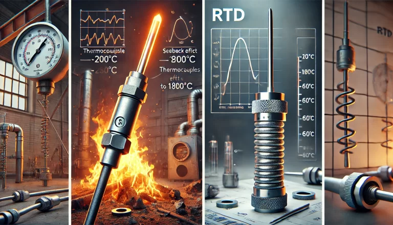
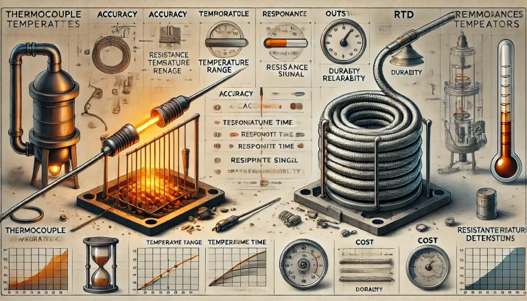
In industrial and laboratory temperature measurements, RTDs (Resistance Temperature Detectors) are widely used due to their accuracy and stability. However, to measure temperature precisely, it’s essential to consider not just the RTD sensor itself, but also the effect of the lead wires connecting the RTD to the measuring instrument.
Lead wires have resistance of their own, and if not properly accounted for, they can introduce significant errors in the temperature reading—especially when the RTD is installed at a distance from the control or measurement system.
To overcome this issue, engineers use 3-wire and 4-wire RTD configurations. This article will explain how these configurations work, how they compensate for lead wire resistance, and which applications they are best suited for.
1. Why Lead Wire Resistance Matters
When you connect an RTD sensor to a measuring device, you’re essentially measuring the total resistance of:
The RTD element itself (which varies with temperature),
Plus the resistance of the connecting lead wires.
Even a small amount of lead resistance can skew the measurement. For example, if you’re using a Pt100 sensor (which is 100 Ω at 0°C), and the lead wire adds just 1 Ω of resistance, the resulting error can be more than 2.5°C.
To maintain accuracy, it becomes essential to cancel out or compensate for this added resistance.
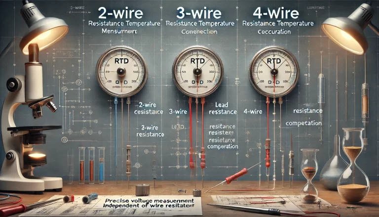
2. Two-Wire RTD Configuration (For Reference)
The simplest method is the 2-wire configuration:
[Instrument] —— Wire A —— [RTD] —— Wire B —— [Instrument]
In this setup, the instrument measures the total resistance of:
RTD + Wire A + Wire B
Problem: There’s no way to distinguish the resistance of the RTD from the resistance of the wires. This configuration is only suitable where:
The lead wires are very short, or
High accuracy is not required.
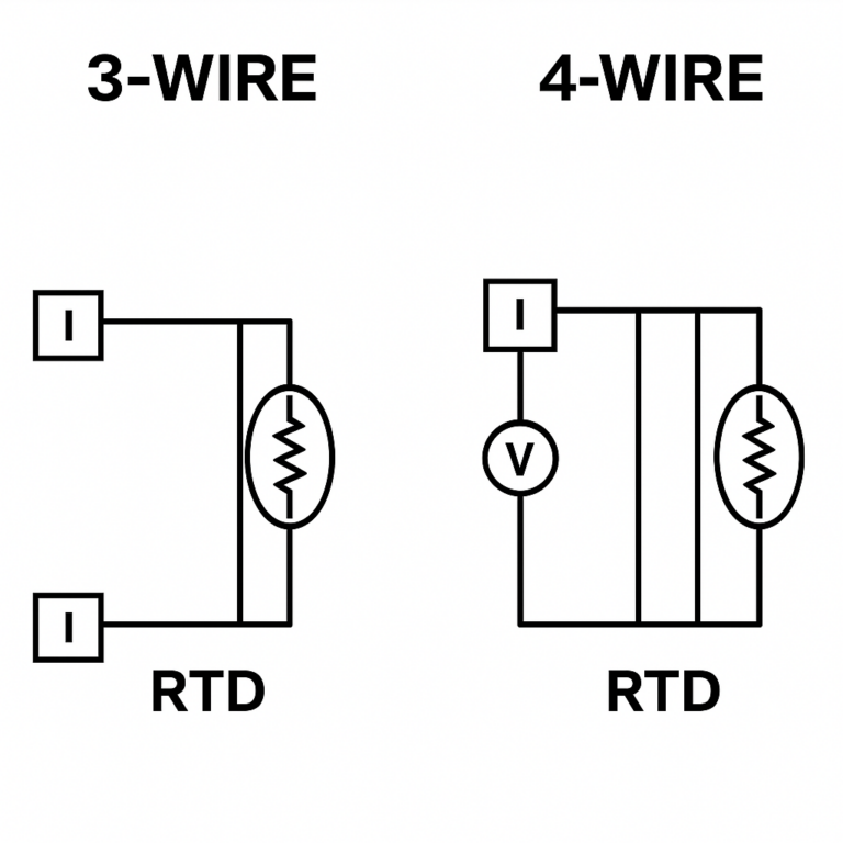
3. Three-Wire RTD Configuration: The Industrial Standard
The 3-wire RTD is the most commonly used configuration in industrial settings. It adds a third wire to help compensate for the lead wire resistance, assuming that all three wires have approximately equal resistance.
🧠 How It Works:
Wire A and Wire B supply current to the RTD.
Wire C connects to one side of the RTD and is used to measure voltage.
The measuring instrument uses a Wheatstone bridge or differential circuit to subtract the resistance of the lead wires.
If the wire resistances are equal, the system can mathematically cancel out the effect of the lead wires.
🔍 Example Logic:
Current flows from the instrument through Wire A into the RTD and returns via Wire B.
The instrument uses Wire C (connected to the same point as Wire A) to measure the voltage drop across the RTD only.
The voltage drop across Wire A and Wire B is assumed equal, so they are subtracted from the final measurement.
✅ Pros:
Effectively compensates for lead wire resistance if wires are well matched.
Cost-effective and simple.
Ideal for most industrial installations.
❗ Caveats:
Assumes all lead wires are identical in resistance.
Still has minor error if lead wires are mismatched or affected by temperature.
4. Four-Wire RTD Configuration: High Precision Measurement
The 4-wire RTD is the most accurate configuration and is often used in laboratory or high-precision applications.
🧠 How It Works:
Two wires (current-carrying wires) are used to supply a known current to the RTD.
The other two wires (voltage-sensing wires) are connected across the RTD element to measure the voltage drop.
Because the voltage measurement circuit draws negligible current, there’s no voltage drop in the voltage-sensing wires, and the instrument measures only the voltage drop across the RTD element itself.
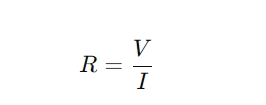
Using Ohm’s Law:
Where:
V= voltage measured directly across the RTD
I= known constant current
This allows for complete elimination of lead wire resistance errors.
✅ Pros:
Extremely accurate.
Completely cancels out lead wire resistance and contact resistance.
Unaffected by lead wire length or temperature.
❗ Cons:
More expensive (requires 4 wires and more complex electronics).
Slightly more difficult to install.
5. Summary Table
Configuration
Number of Wires
Accuracy
Lead Resistance Compensation
Typical Use
2-Wire
2
Low
None
Low-cost, short distance
3-Wire
3
Medium
Partial (assumes equal wires)
Industrial standard
4-Wire
4
High
Full
Precision/lab
6. Final Thoughts
When selecting an RTD configuration, consider:
Required measurement accuracy
Distance between sensor and instrument
Budget
Environmental conditions
In industrial applications where wiring and cost must be balanced, the 3-wire RTD offers a practical and reasonably accurate solution. For high-precision laboratory work, 4-wire RTDs are the gold standard, eliminating nearly all measurement uncertainty caused by lead wire resistance.