Transducer Mounting Allocation
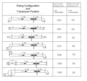
The first step in the installation process is to select an optimal location for installing the transducers in order to make the measurement reliable and accurate. A piece of basic knowledge about the piping and its plumbing system would be advisable. An optimal location would be defined as a long straight pipeline full of liquid that is to be measured. The piping can be in a vertical or horizontal position. The following table shows examples of optimal locations.
Principles to select an optimal location:
- The straight pipe should be long enough to eliminate the irregular-flow-induced error. Typically, the length of the straight pipe should be 15 times the pipe diameter. The longer the better. The transducers should be installed at a pipe section where the length of the straight pipe on the upstream side is at least 10D and on the downstream side is at least 5D. Besides, the transducer installation site should be at least 30D away from the pump. Here D stands for pipe outer diameter. Refer to the following table for more details.
- Make sure that the pipe is completely full of liquid.
- Make sure that the temperature on the location does not exceed the range for the transducers. Generally speaking, the closer to the room temperature, the better.
- Select a relatively new straight pipeline if it is possible. Old pipe tends to have corrosions and depositions, which could affect the results. If you have to work on an old pipe, we recommend you treat the corrosions and depositions as if they are part of the pipe wall or as part of the liner. For example, you can add an extra value to the pipe wall thickness parameter or the liner thickness parameter to take into account the deposition.
- Some pipes may have a kind of plastic liner which creates a certain amount of gaps between the liner and the inner pipe wall. These gaps could prevent ultrasonic waves from direct traveling. Such conditions will make the measurement very difficult. Whenever possible, try to avoid this kind of pipe. If you have to work on this kind of pipe, try our plug-in transducers that are installed permanently on the pipe by drilling holes on the pipe while the liquid is running inside.
FIGURE 5: PIPE CONFIGURATION AND TRANSDUCER PLACEMENT
Transducer Installation
The transducers used by the ultrasonic flow meter are made of piezoelectric crystals both for transmitting and receiving ultrasonic signals through the wall of the liquid piping system. The measurement is realized by measuring the traveling time difference of the ultrasonic signals. Since the difference is very small, the spacing and the alignment of the transducers are critical factors to the accuracy of the measurement and the performance of the system. Meticulous care should be taken for the installation of the transducers.
Steps to the installation of the transducers:
Locate an optimal position where the straight pipe length is sufficient (see the previous section), and where pipes are in a favorable condition, e.g., newer pipes with no rust and ease of operation. Clean any dust and rust on the spot where the transducers are to be installed. For a better result, polishing the pipe outer surface with a sander is strongly recommended. Apply adequate ultrasonic couplant (grease, gel, or Vaseline)* on to the transducer transmitting surface as well as to the installation spot on the pipe surface. Make sure there is no gap between the transducer transmitting surface and the pipe surface.
Extra care should be taken to avoid any sand or dust particles left between the pipe surface and the transducer surface.
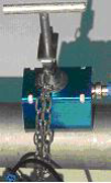
Horizontally lined pipes could have gas bubbles inside the upper part of the pipe. Therefore, it is recommended to install the transducers horizontally by the side of the pipe. There are three ways to mount the transducers on the pipe: by magnetic force, by the clamp-on fixture, and by hand. If the pipe material is metal, the magnetic force will hold the transducer on the pipe. Otherwise, you may either simply hold the transducer handle and press it against the pipe (for S-type only) if you just need a quick measurement, or, you may use or a metal strip or the provided clamp fixture to install the transducers (see the figure on the right.)
FIGURE 6: TRANSDUCER CLAMPDOWN
*Note: It is recommended to use the Conductive Gel product from Livingstone, as the ultrasonic couplant for safety considerations. Other couplants, such as grease, gel, and Vaseline, can be used as alternatives, but at your own risk.
Transducer Spacing
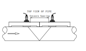
The spacing value shown on menu window M25 refers to the distance of inner spacing between the two transducers (see the following figure). The actual distance of the two transducers should be as close as possible to this spacing value.
V Method Installation V-method installation is the most widely used method for daily measurement with pipe inner diameters ranging from 20 millimeters to 300 millimeters. It is also called the reflective method.
FIGURE 7: TRANSDUCER V METHOD MOUNTAIN
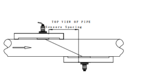
Z Method Installation Z-method is commonly used when the pipe diameter is between 100 millimeters and 500 millimeters. This method is the most direct for signal transfer and can therefore provide better results than the V method on many applications. FIGURE 8: TRANSDUCER Z METHOD MOUNTING
W Method Installation W-method is usually used on plastic pipes with a diameter from 10 millimeters to 100 millimeters. This method can be effective on smaller pipes that have internal deposits.
FIGURE 9: TRANSDUCER W METHOD MOUNTING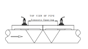
Installation Testing
After completion of the transducer installation, the user should check the following items: the receiving signal strength, the signal quality Q value, the delta time (traveling time difference between the upstream and the downstream signals), the estimated liquid sound speed, the transit time ratio, and etc. As such, one can be sure that the flowmeter is working properly and the results are reliable and accurate.