Typical Pneumatic Circuit Configurations for Control Valves - Just Measure it

Typical Pneumatic Circuit Configurations for Control Valves

1. Introduction

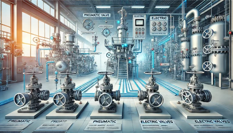
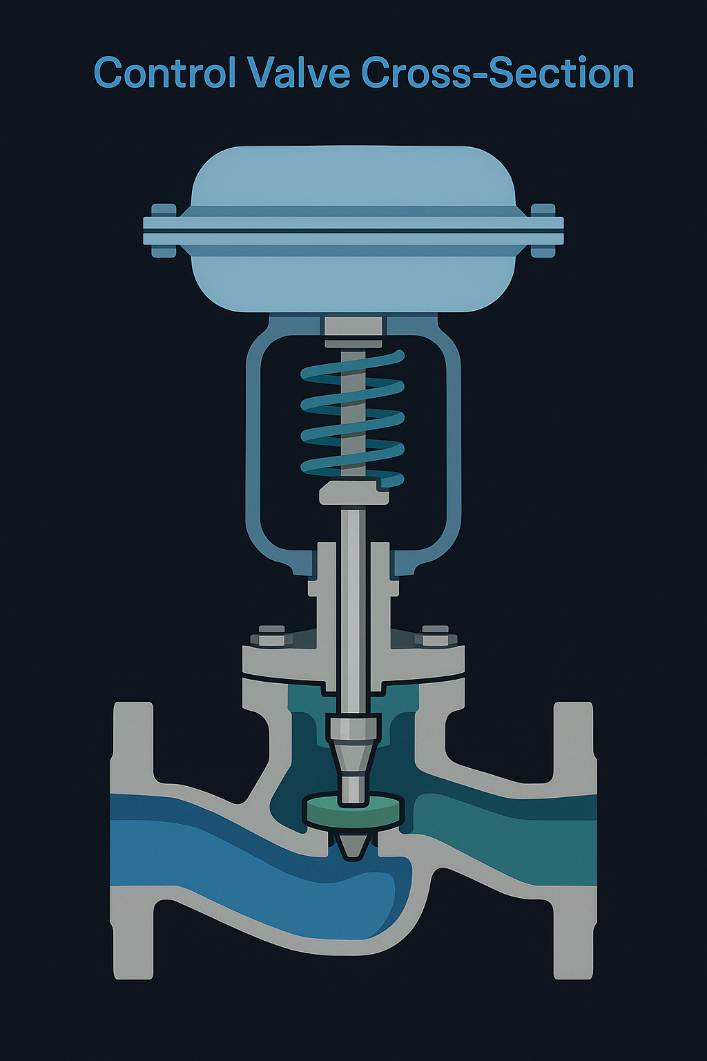
Control valves are the final control elements in process automation, typically consisting of an actuator, valve body, internal trim, and accessories.
Accessories such as positioners, solenoid valves, quick exhaust valves, and air reservoirs are critical in ensuring reliability, safety, and fast response. This document summarizes the key accessories and demonstrates typical pneumatic circuit configurations for anti-surge control systems.

2. Classification of Control Valve Accessories

2.1 Signal & Control Devices

  • Valve Positioner

    • Types: pneumatic, electro-pneumatic, smart positioners

    • Function: ensures accurate valve position through feedback control

  • Solenoid Valve

    • Used in remote control, interlock, and emergency shutdown

    • Configurations: direct-acting, pilot-operated, 3/2-way, 5/2-way

  • Limit Switch

    • Provides ON/OFF position feedback for interlocks and alarms

    • Figure 3 — Mechanical vs. Proximity Limit Switch

  • Valve Position Transmitter

    • Converts stem travel or angle into 4–20 mA signal for monitoring

2.2 Air Supply & Pressure Regulation

  • Filter Regulator (FR)

    • Removes impurities, stabilizes supply pressure

  • Air Reservoir (Tank)

    • Provides backup air supply in case of source failure

    • Ensures valve completes fail-safe action

  • Check Valve

    • Allows airflow in one direction, prevents backflow

  • Quick Exhaust Valve

    • Accelerates actuator response by venting directly to atmosphere

  • Volume Booster / Amplifier

    • Increases air flow to actuator for rapid stroke response

  • Air Lock Valve (Fail Position Holder)

    • Maintains valve position during air failure

3. Typical Pneumatic Circuits

3.1 Anti-Surge Valve for Compressors (≤14″ Size)

  • Normal Operation:

    • 4–20 mA signal → Positioner → Solenoid Valve → Booster → Actuator

    • Valve modulates smoothly according to signal

  • Fast-Open Function:

    • Solenoid de-energizes → Quick exhaust valve + solenoid venting → Valve rapidly opens

3.2 Anti-Surge Valve for Large Compressors (>20″ Size)

  • Normal Operation:

    • Digital positioner output → Pneumatic relay (377) → Booster → Double-acting actuator

  • Fast-Open Function:

    • Solenoid & relay cut air supply, air reservoir discharges → Quick exhaust venting → Valve rapidly opens

4. Engineering Notes & Best Practices

  • Select accessories according to safety integrity level (SIL) requirements

  • Ensure explosion-proof rating and IP protection level meet site standards

  • Redundancy:

    • Safety priority: series logic for solenoid valves

    • Availability priority: parallel logic

  • Install pressure gauges for monitoring air lock and actuator chamber pressures

  • Reserve space for maintenance and inspection when installing air tanks and pipelines

5. Conclusion

A properly designed pneumatic circuit with suitable valve accessories enhances:

  • Safety (fail-safe positioning, interlock reliability)

  • Responsiveness (fast opening/closing functions)

  • Reliability (clean air supply, redundancy design)

  • Maintainability (standardized accessories, clear layout)

By understanding and correctly applying these components, engineers can ensure stable process control and protect critical equipment such as compressors.

Share This Story, Choose Your Platform!

Contact Us

    Please prove you are human by selecting the house.
    Translate »