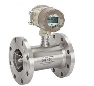
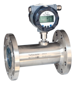
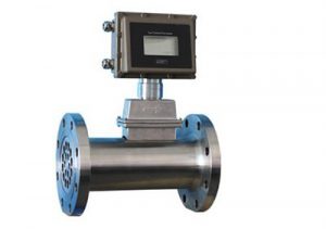
(1) Digital signal output The output of the turbine flowmeter is a pulse digital signal proportional to the flow rate. The advantages are easy to accumulate and easy to send into the computer system.
Pulse output type:
①-General working voltage: +12VDC or +24VDC two kinds (the power supply must be selected before ordering).
②Signal transmission distance: less than 250m.
③Type of output signal: square wave signal.
④ Output signal amplitude: + 12VDC power supply amplitude is about 10V,+24VDC power supply amplitude is about 20V.
⑤Sensor installation: connect the amplifier to the turbine flow sensor. After the turbine flow sensor is installed, put the amplifier Screw it to the turbine flow sensor, and tighten the lock nut after the amplifier reaches the end.
⑥Output signal wiring: pulse output type amplifier has three external leads, a positive power supply (such as red wire), pulse output (Such as white wire) connect with other display instruments or equipment, and ground the shield.

(2)
Analog signal output
Current output type (4 -20) mA:
①Working voltage: external power supply +24VDC (generally a two-wire system)
②Output signal: (4-20)mA or (1~5)V, 4mA corresponds to zero flow of turbine flow sensor, 20mA corresponds
The maximum flow rate of the turbine flow sensor and the flow range are shown on the nameplate of the turbine flow sensor.
③Signal transmission distance: less than 250m.
④ Installation: After the turbine flow sensor is installed, screw the amplifier to the connector of the full-wheel flow sensor.
Tighten the lock nut after reaching the bottom.
⑤ Wiring: (4-20) mA output type amplifier external leads (such as red wire and white wire).

(3) On-site display type
①Display six-digit instantaneous flow and ten-digit cumulative total. The first line displays the instantaneous flow rate, and the second line displays the cumulative value.
②Using EEPROM technology can store the cumulative total and the instrument system.
③Display accuracy: ±1 display unit.
④Signal output: pulse output: (0 -5000) Hz (adjustable) external +24V power supply DC;
Current output: (4-20)mA external +24V power supply DC (two-wire system).
⑤Small signal removal function.

(4) Signal transmission line requirements
In order to ensure that the full display instrument has sufficient sensitivity to the pulse signal output by the turbine sensor, it is necessary to increase the signal-to-noise ratio.
Therefore, various electrical interference phenomena should be prevented during installation, namely electromagnetic induction, electrostatic and capacitive coupling. Therefore, in the configuration signal transmission
When powering the line, you must pay attention to the following points:
①Limit the maximum length of the signal line. The maximum length of the signal line is L=dV, where V is the sensor at the minimum flow
The effective value of the output voltage of the coil, mV; d is the coefficient, m/mV. Its value can be taken: when V<100mV, d=1.0;
When 1000mV<d<5000mV, d=1.5; When V>5000mV, d=2.0.
②The signal transmission line should be shielded cable to prevent inductive noise from outside. The transmission cable is required to be at the end of the display instrument.

The shield is grounded. The transmission cable should not be close to the strong electromagnetic equipment, and it is not allowed to be arranged in parallel with the power line.
Wiring: The pulse output amplifier has three external leads, such as red wire, white wire, and a shield. The red wire is connected to the positive power supply, since the line is for pulse output to connect with other displays or equipment, and the screen is grounded.
Note: Please be sure to complete all wiring and check whether the wiring is correct before turning on the power.
Do not reverse the connection, otherwise, the amplifier board may be easily damaged.
