Overview
This guide outlines the fault analysis steps for four key measurement control systems: temperature, pressure, flow, and level control systems. Each system is analyzed based on specific fault scenarios, providing clear steps to diagnose and address common issues.
1. Fault Analysis of the Temperature Control System
When analyzing faults in the temperature control system, it is important to note that temperature measurement instruments often experience significant time delays.
Common Fault Scenarios:
Sudden Maximum or Minimum Reading:
If the reading jumps to the maximum or minimum suddenly, it is typically a fault in the instrument. Since temperature systems have a large time lag, sudden changes are unlikely. Most likely causes include broken thermocouple or resistance temperature detector (RTD) compensating wires or malfunctioning transmitters.Rapid Oscillation:
Rapid oscillations on the temperature record are often caused by improper PID (Proportional-Integral-Derivative) tuning. Adjusting the PID parameters may resolve this issue.Significant Fluctuations:
Large fluctuations in temperature reading, especially when no significant changes occur in process conditions, often indicate an instrument fault. If the fluctuations reduce significantly when switched to manual mode, the fault is likely in the controller; otherwise, it may lie in the amplifier.Erratic Recordings:
If the instrument’s graph shows straight lines or drifts unexpectedly, it may be a false indication. A quick test involves moving the measuring wire to check if there’s any resistance or torque in the system. If there is no resistance or insufficient torque, the fault is in the instrument.Suspected Measurement Errors:
If the temperature values are suspected to be incorrect, the technician can switch the controller to manual mode and use a standard thermometer to verify readings.Drifting Outputs:
If the output drifts without a significant change in temperature, it usually points to a malfunctioning amplifier or issue in the output loop.Controller Output Issues:
If the controller output cannot return to zero or shows a large contrast, there may be an issue within the controller itself.
System-Specific Faults:
Control Valve: Check if the input signal to the control valve is fluctuating. A steady signal with no changes indicates a fault with the valve’s diaphragm or positioning system.
Regulator and Positioner: If the input signal to the positioner changes while the output remains the same, the positioner itself may be faulty.
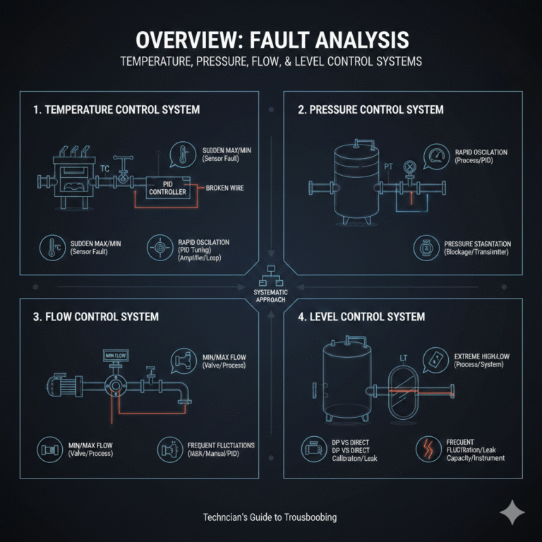
2. Fault Analysis of the Pressure Control System
Common Fault Scenarios:
Rapid Oscillation:
If the pressure control system exhibits rapid fluctuations, first check if there were any process changes. If the process is stable, then the issue might be with the PID tuning of the regulator.Pressure Stagnation:
If the pressure does not change despite variations in process operations, check the pressure measurement system. It’s likely that there’s a blockage in the pressure measuring tubing or an issue with the pressure transmitter.
3. Fault Analysis of the Flow Control System
Common Fault Scenarios:
Minimum Flow Indicator:
If the flow indicator shows a minimum reading, first check the local instrument. If it also reads minimum, inspect the control valve position. A zero valve opening indicates a valve fault. If the valve position is correct, check for low system pressure, blockages in the piping, or issues with pumps or media crystallization.Maximum Flow Indicator:
If the flow indicator shows the maximum value, manually adjust the control valve to decrease the flow. If the flow reduces, the fault is likely in the process. If the flow does not decrease, the fault may lie within the measurement system or valve action.Frequent Flow Fluctuations:
If the flow readings fluctuate frequently, switch the control to manual mode. If the fluctuations decrease, the fault is in the instrument or the PID parameters need adjustment. If the fluctuations continue, it indicates a process-related fault.
4. Fault Analysis of the Level Control System
Common Fault Scenarios:
Extreme High or Low Level Readings:
If the level indicator shows extreme high or low readings, first check if the system can stabilize with manual control. If the level remains unstable, the fault is likely process-related. Otherwise, it points to an issue with the level control system itself.Discrepancy Between Differential Pressure and Direct Readout:
If the differential pressure transmitter’s reading does not match the direct readout, check if the direct readout device is functioning properly. If it is, inspect the differential pressure transmitter for possible leakage in the capillary tube or improper zero calibration.Frequent Level Fluctuations:
Frequent fluctuations in level readings may indicate issues with the control system if the system’s capacity is large. For smaller systems, it may be a process issue. If no process changes are detected, further inspection of the instrument is needed.
Conclusion
This fault analysis guide provides a systematic approach to troubleshooting temperature, pressure, flow, and level control systems. By following these steps, technicians can identify the root causes of various issues and take appropriate actions to restore normal system operation.