1. How to distinguish between major and minor faults?
- Issue: The distinction between major and minor faults lies in the system’s response. For minor faults, the system emits an alarm signal, and the fault indicator flashes. For major faults, the system emits a fault signal, the fault indicator stays on, and it sends a command to cut off the high voltage and inhibit the circuit breaker.
- Solution: As long as the major fault is not cleared, the fault indication and high voltage cut-off command remain effective. The cause of the fault needs to be identified and resolved.
2. What are the minor faults?
- Minor faults include transformer over-temperature alarms, cabinet temperature over-temperature alarms, cabinet door open, and unit bypass.
- The system does not store minor faults; the alarms are automatically cleared once the fault disappears. When a minor fault alarm occurs during inverter operation, the system will not shut down.
3. What are the major faults?
- Major faults include external faults, transformer overheating, cabinet overheating, unit faults, inverter overcurrent, high voltage power loss, etc.
- For external faults, the high voltage disconnection must be cleared before resetting the system. Other major faults can be reset directly, but the fault cause must be identified. After a unit fault, only by reapplying high voltage can the unit status be detected. If the fault is difficult to analyze and it is unclear whether high voltage can be reapplied, consult the manufacturer.
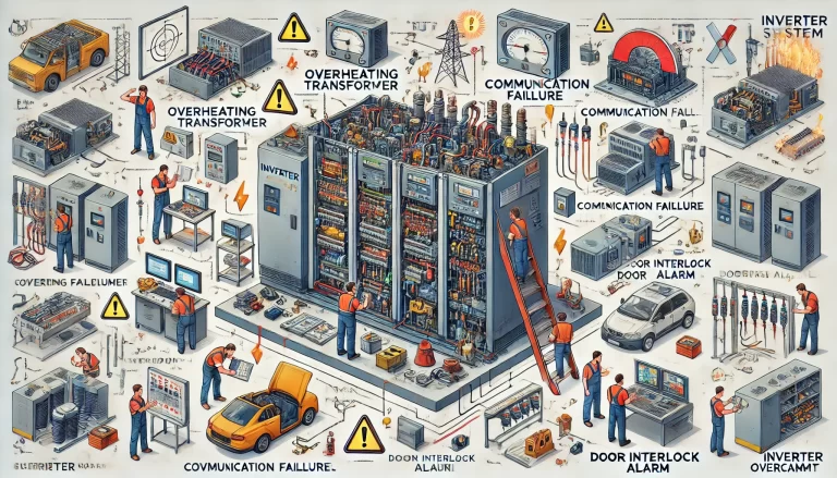
4. Transformer Over-temperature Alarm
- Symptom: When the temperature measured by the transformer temperature controller exceeds the set alarm temperature (default is 100°C), the over-temperature alarm contact closes.
- Solution: Check if the fan at the top or bottom of the transformer cabinet is working properly (if the bottom fan is not working, the temperature difference between the three phases may be significant). Check if the temperature sensor is normal, if the filter screen is clogged, if the inverter has been operating in an overload state for a long time, if the ambient temperature is too high, if the fan switch and contactor installed at the bottom front of the transformer cabinet are off, and if the fan control and protection circuit of the transformer cabinet are normal.
5. Cabinet Over-temperature Alarm
- Symptom: When the temperature at the temperature measurement point of the unit cabinet exceeds 55°C, the system emits a cabinet over-temperature minor fault alarm.
- Solution: Check if the top fan of the unit cabinet is working properly, whether the fan switch installed in the secondary room has tripped, if the filter screen is clogged, if the inverter has been operating in an overload state for a long time, if the ambient temperature is too high, and if the fan control and protection circuit of the transformer cabinet are normal.
6. Transformer Overheating
- Symptom: When the temperature measured by the transformer temperature controller exceeds the trip temperature (default is 130°C), the trip contact closes, and the system reports a transformer overheating major fault.
- Solution: Check the temperature displayed by the temperature controller and the alarm value settings. Other inspection items are the same as for the transformer over-temperature alarm.
7. Cabinet Overheating
- Issue: The temperature at the temperature measurement point of the unit cabinet exceeds 60°C.
- Solution: Follow the same steps as for the cabinet over-temperature alarm.
8. Cabinet Door Interlock Alarm
- Issue: The travel switch and cabinet door pressing part are not tightly fitted.
- Solution: Check the “pre-travel” and “over-travel” of the travel switch, and whether the electrical function is normal. If not, replace the interface board.
9. Controller Communication Failure
- Issue: The communication cable between the monitor control board and the main control board is connected incorrectly.
- Solution: Confirm that the communication cable is correctly connected. Check the voltage on the monitor control board, and if necessary, replace the main control board or monitor.
10. Main Control Board Fault
- Issue: The monitor detects a fault on the main control board.
- Solution: Replace the monitor or main control board.
11. Interface Board Communication Failure
- Issue: The monitor and interface board have not established communication. The interface board resets the monitor every 5 seconds. If communication is not established within 3 minutes and 30 seconds, it is considered a major fault.
- Solution: Check the communication cable, wiring terminals, I/O board working status, and voltage. If necessary, replace the interface board.
12. Parameter Error
- Issue: When modifying parameters, if the set parameters are incorrect (this fault may be reported during synchronous vector control), a parameter error is reported.
- Solution: Re-modify the parameters and press the reset button.
13. External Fault
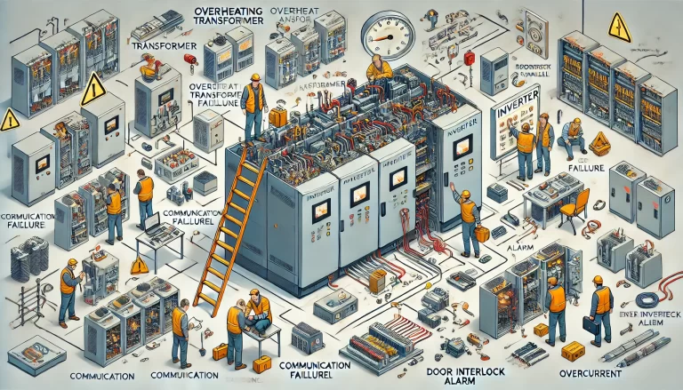
- Symptom: The high-voltage disconnection button or high-voltage disconnection contact on the interface board is closed, and the system reports an external fault.
- Solution: Check the high-voltage disconnection button and terminal. If necessary, replace the interface board.
14. High-Voltage Power Loss
- Issue: The upper-level high-voltage power source is lost.
- Solution: Check the circuit breaker in the upper-level switchgear.
15. Inverter Overcurrent
- Issue: The inverter output current exceeds 1.5 times the rated current, triggering overcurrent protection.
- Solution:
- Check if the output voltage detection board is normal and if there are any visible short circuits or discharge marks.
- Ensure that the fiber optic cables are securely connected and that the main circuit connecting screws are tightened.
- Verify if the Hall sensor power supply is normal and if the Hall sensor output current signal is correct.
- Check if the acceleration time is too short, torque boost is too high, or starting frequency is too high.
- Ensure the motor or load is not blocked, and that the motor windings and output cable insulation are intact.
- Ensure all units are operating normally.
- Verify that the input power supply voltage is not too low.
- Ensure there are no power factor correction capacitors or surge absorbers on the inverter output side.
- Check for short circuits or damage to the unit detection board.
16. Motor Overcurrent
- Issue: The inverter output current exceeds 1.2 times the motor’s rated current and continues for more than 2 minutes.
- Solution: Check the parameter settings, ensure the motor and mechanical load are not stuck, and verify that the power supply voltage is not too low.
17. Motor Not Rotating After Inverter Starts
- Solution:
- Check for issues with the inverter output contactor or switch devices.
- Inspect the connection of the inverter output cable, monitor the output current and voltage. If there is voltage but no current, it indicates an open circuit in the main circuit between the inverter and the motor. If there is both voltage and current, check for single-phase grounding in the cable or an open circuit in the motor rotor winding.
18. Unit Major Fault
- Issue: Includes fuse fault, drive fault, unit overheating, unit overvoltage, and fiber optic fault.
- Solution: Investigate and address the fault based on the specific type.
19. Fuse Fault
- Issue: Detected when the unit is missing a phase.
- Solution: Check the main power supply, verify that the three-phase input wiring is secure, and inspect the input fuses.
20. Drive Fault
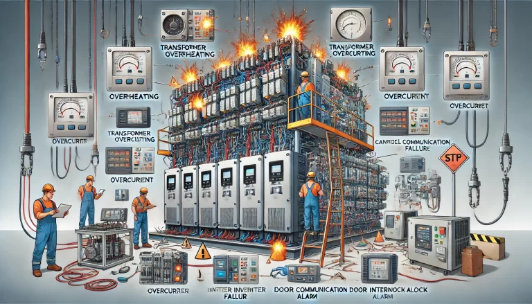
- Solution: Check for short circuits in the voltage detection board, short circuits at the power unit’s output terminals L1 and L2, motor insulation condition, and possible mechanical faults in the load.
21. Unit Overheating
- Issue: The temperature of the heatsink inside the unit exceeds 85°C.
- Solution: Check if the fan on top of the cabinet is working properly, whether the unit cabinet fan switch has tripped, whether the filter is blocked, if the unit has been operating under overload conditions for an extended period, and if the ambient temperature is too high.
22. Unit Overvoltage
- Issue: The DC bus voltage exceeds the protection value.
- Solution:
- Check if the input high voltage power supply exceeds the allowed maximum value (if the supply voltage is too high, adjust the transformer tap to 105%).
- If overvoltage occurs during deceleration, appropriately increase the inverter’s deceleration time setting.
23. Fiber Optic Fault
- Issue: The system cannot detect unit communication.
- Solution: Check if the power supply to the power unit is normal, and verify that the fiber optic connectors on both the power unit and the controller are secure and not damaged.
24. Unit Bypass
- Issue: When the unit is equipped with bypass hardware and the bypass level in the parameter settings is not zero, if the unit experiences a drive fault, fuse fault, or unit overheating, a bypass will occur.
- Solution: When unit bypass occurs, the cause must be identified, and the faulty unit should be replaced as soon as possible. (For the remaining two phases, the bypassed units do not need to be replaced.) Clean the unit drive board and control board. Excessive dust on these boards can cause false alarms.
25. Inconsistent Operating Frequency and Given Frequency
- Solution:
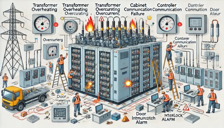
- If the inverter output current exceeds the set current limit, the inverter automatically reduces the frequency to lower the output current and prevent overcurrent protection from tripping. This usually happens when the input voltage is too low or the load increases suddenly.
- In the event of a momentary power outage, to maintain control of the motor, the inverter will automatically decelerate and obtain energy from the motor.
- Check for faults in the Hall element, unit detection board, or signal board.
26. Black Screen on the Monitor
- Solution: Check if the power terminals are disconnected, if the connecting cables are loose, if the power supply voltage is normal, and if the monitor wiring is damaged.
27. Parameters Cannot Be Modified
- Issue: During operation, most parameters cannot be modified. If the parameter modification option in the functional parameters is set to “Prohibited,” then all parameters except the given frequency or specified quantity cannot be modified.
28. Inverter Automatically Restarts After Shutdown
- Issue: In remote control mode, starting and stopping can only be controlled through remote terminals.
- Solution: If the startup method in the parameter settings is set to “Level Start” (close to start, open to stop), during an emergency stop, when the stop signal is cut off or the inverter is stopped by other means, the inverter will immediately perform a free stop. However, when the emergency stop signal closes again, because the remote start level signal is still present, the inverter will automatically start running.
29. Inverter Trips as Soon as Power Is Applied
- Issue: When power is applied to the inverter, due to the magnetizing inrush current of the transformer and the charging of the unit capacitors, the instantaneous current value can reach 6-7 times the rated current of the inverter, lasting for tens of milliseconds. If the current protection setting of the upstream circuit breaker is too small, it will cause the upstream switch to trip.
- Solution: Adjust the fast-acting protection setting of the upstream switchgear.
30. Oscillation in Output Frequency During Startup
- Issue: The motor current fluctuates significantly at low speed.
- Solution: Increase the current limit setting, shorten the startup time, or replace units with lower output voltage.
30. Oscillation in Output Frequency During Startup
- Issue: The motor current fluctuates significantly at low speed.
- Solution: Increase the current limit setting, shorten the startup time, or replace units with lower output voltage.
32. Induced AC Voltage on External Terminals
- Issue: Induced voltage appears on remote start/stop, high-voltage disconnection, and system reset signal lines.
- Solution: Separate the wiring, use shielded cables, rewire, and use capacitors to eliminate induced voltage.
