1.General Introduction
It adopts mature and reliable force weighing sensor technology, which can integrate the flow rate and flow (or optimize the temperature and pressure detection of the working condition) according to the characteristics of the working condition, which fully reflects the integration of today’s electromechanics High-tech and cost-effective of chemical products. The data processing of the instrument system adopts Microchip’s MCU technology combined with modern microelectronics technology to develop a highly reliable and accurate industrial flow measurement and control instrument.
2. Structure and measurement principle:
1. Structure
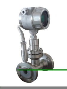
The sanitary clamp-type target flowmeter is mainly composed of a measuring tube (housing), a new type of sensor (including flow-blocking elements), an integrated display, and an output part. According to different media and working conditions, suitable sensors must be selected. Therefore, users provide accurate measurement objects and parameters, and the selection of appropriate sensors by manufacturers is the key to whether the product can be accurately measured.
2.Measuring principle
The sanitary target type flowmeter is the pressure difference generated when the medium is flowing in the measuring tube due to its own kinetic energy passing through the baffle (target type flowmeter) and has a force on the baffle, and its force size. It is proportional to the square of the medium flow rate, and its mathematical expression is as follows:
F=CdAρV2/2
In the formula: the force of the F choke (kg)
Cd object drag coefficient
A The axial projected area of the baffle on the measuring tube (mm2)
Medium-density under ρ working condition (kg/m3)
The average velocity of V medium in the measuring tube (m/s)
The force F received by the baffle (target) is transmitted to the sensor through the rigidly connected transmission member (measurement rod), and the sensor generates a voltage signal output: V=KF
In the formula: V—the output voltage of the sensor (mV), K—the proportional constant, F—the force of the baffle (target) (kg),
After this voltage signal is pre-amplified, AD converted and processed by a computer, the corresponding instantaneous flow, and cumulative total can be obtained.
3. Applicable occasions:
The typical application has syrup, milk, edible oil, purified water, corn syrup, grain syrup, high-purity water, fruit juice, wort, toothpaste, shampoo, detergent, aromatic oil, grease, and other liquid foods.
4. Performance characteristics:
1. The entire instrument has no moving parts in the design, and the installation is simple and maintenance-free.
2. The third-generation capacitive force sensor is adopted, which has reliable performance, high precision, and sensitivity.
3. The pressure loss is small, only about 1/2△P of the standard orifice plate.
4. Dirt-resistant, non-clogging, anti-vibration, electromagnetic interference, strong anti-impurity ability, can replace differential pressure flowmeter.
5. A variety of anti-corrosion and high and low-temperature resistant materials (such as Hastelloy, titanium, etc.) can be used.
6. The whole machine can be made into a fully sealed, no dead angle (welded form), without any leakage points, and can withstand the high pressure of 42MPa.
7. The self-checking procedure is set in the instrument, and the fault phenomenon is clear at a glance.
8. The sensor is not in contact with the measured medium, there is no wear of parts, and it is safe and reliable to use.
9. The dry calibration method can be used on the spot, that is, the weight hanging method is used. The single key operation can complete the calibration.
10. There are a variety of installation methods to choose from, such as an online plug-in, the installation cost is low.
11. With integrated temperature and pressure compensation, directly output quality or standard;
12. With optional small-signal removal, non-linear correction, filter time can be selected.
13. It can accurately measure the flow of gas and liquid under various conditions of normal temperature, high temperature 500 degrees, and low temperature -200 degrees.
14. The measurement is accurate, and the accuracy can reach 0.2%.
15. Good repeatability, generally 0.05~0.08%, fast measurement.
16. The flow rate range can be changed by replacing the baffle (target) according to actual needs;
17. Low-power battery on-site display, which can directly read the displayed value online, and the display screen can read instantaneous and cumulative flow and percentage bar graphs at the same time.
18. The installation is simple and convenient, and it is extremely easy to maintain.
19. Multiple output forms, capable of transmitting various parameters remotely.
20. Strong anti-vibration, pulsating flow can be measured within a certain range.
5. Technical indicators:
1. Applicable medium: syrup, milk, edible oil, purified water, and other liquids with hygienic requirements.
2. Caliber: DN15~DN50mm.
3. Nominal pressure: 0.6~42MPa.
4. Working condition temperature: -20~+300℃ (medium temperature type), -20~+500℃ (high-temperature type), higher temperature, and factory customization.
5. Accuracy: ±1.5%FS.
6. Measuring range ratio: 1:10.
7. Shell material: carbon steel; stainless steel.
8. Power supply mode: built-in 3.6VDC lithium battery (replace once every two years); external supply 24VDC (optional).
9. Output signal: 4~20mA two-wire system; pulse 0~1000HZ; RS232/RS485 (or negotiated according to user requirements).
10. Protection level: IP65.
11. Explosion-proof mark: intrinsically safe ExiallCT4; explosion-proof ExdllCT4.
12. The meter head shows cumulative flow; instantaneous flow; bar-shaped full-scale percentage; fault self-check.
13. Connection method: clamp connection (DN15-50mm).
6. Installation instructions:
1. Normal temperature, low temperature, and high-temperature flow meters can be installed horizontally, vertically, or inverted according to different working conditions (subject to the factory calibration sheet).
2. When the working temperature of the medium is above +300 degrees, the user should take heat insulation measures for the flowmeter housing to prevent heat radiation from damaging the meter head (the working temperature of the meter head is -30 to +70 degrees), and the same applies to the working temperature below -100 degrees. Anti-freezing measures should also be taken for the medium.
3. In order to ensure the accurate measurement of the flowmeter, it is required to set the front and rear straight pipe sections.
4. In order to ensure that the flowmeter does not affect the operation of the system during inspection and replacement, the bypass valve (3) and shut-off valve (1, 2) should be set as far as possible.
5. Vertical installation can be adopted due to process requirements, and the flow direction of the measured medium can be from bottom* or top to bottom, but it should be explained to the supplier when ordering.
6. The diameter of the flowmeter and the diameter of the connected pipe should be the same as possible to reduce flow interference and cause measurement errors.
7. The housing of the flowmeter must be grounded reliably. If there is no grounding condition, please explain to the manufacturer.
7. Installation matters needing attention:
1. There should be straight pipe sections before and after the measuring pipe. The pipe diameter of the straight pipe section should be the same as that of the flow meter measuring pipe. If the pipe diameters are different, use a reducer to connect to make the pipe diameter at the entrance the same. The length of the straight pipe section on the upstream side of the flowmeter is generally not less than 6~20D, which is determined by different upstream choke types, and the downstream straight pipe section is not less than 3-4D. The flowmeter is usually calibrated according to the horizontal position and is generally installed in a horizontal pipeline. When it must be installed in a vertical pipeline, the vertical installation state of the flowmeter must be verified by the hanging weight method, and the fluid direction should be from bottom to top.
2. In order to facilitate maintenance and use and prevent one-way force when the flowmeter is activated, a bypass pipe is installed in parallel to installing a drain pipe downstream of the flowmeter, which is convenient for cleaning and purging the instrument and is more suitable for measuring dirty fluids or media that are easy to solidify and crystallize. necessary. The target plate and the measuring tube (meter body) should be installed coaxially. According to the test of a certain caliber, if the target plate center and the pipe center deviate 1mm up and down, it may cause a deviation of 1% to 2% of the flow coefficient, but the left and right deviations are 1mm. , The impact is not obvious.
3. When installing an explosion-proof target type flowmeter, pay attention to check whether there is an explosion-proof mark and an explosion-proof certificate and whether the explosion-proof equipment is intact.
4. For small-caliber flowmeters, the flowmeter is relatively heavy due to its small diameter. In order to prevent the pipeline from deforming or vibrating during operation, an additional bracket should be provided to support the flowmeter. For large-caliber flowmeters, no additional support is necessary.
8. Precautions for use:
1. Before the fluid flows, close the downstream valve of the flowmeter and open the upstream valve to let the fluid enter the flowmeter pipe section. Then slowly open the downstream valve of the flowmeter and close the bypass valve at the same time to make the fluid increase slowly. Do not open the valve suddenly and impact the target plate to damage the meter.
2. After the flowmeter* is running, in addition to cleaning the scale of the target plate and measuring tube, the hanging weight method should be used to check whether the characteristics of the force converter have changed. The hanging weight method is to apply the weighted gravity in the same direction as the flow in the center of the target board, adjust the meter, and adjust the force corresponding to the upper limit of the flowmeter flow rate, that is, F1 calculated according to formula (16.6), and other flow points add related weights, Read the output signal of the instrument, check the basic error and linearity of each point. The “hanging weight method” is described in the manufacturer’s product manual or other materials ‘and you can also refer to it.
3. There is still a difference between the force of the fluid acting on the target plate and the force of the hanging weight, so the hanging weight method cannot completely replace the real flow calibration. To obtain high accuracy, the necessary real-flow calibration is still required.
4. When copying or modifying the target plate, pay attention to the processing accuracy of the target plate, otherwise, it will affect the flow coefficient. The test data proves that for the target flowmeter with port=0.8 when the pipe diameter is DN=25mm if the target diameter deviation is 0,03mm, the flow coefficient deviation is 1%. The machining accuracy and surface roughness of the target plate also affect the flow coefficient.
5. When the flow meter is running, if the output value is found to be swaying, check that the force conversion system is normal, it may be caused by the vortex street generated by the fluid flowing through the target plate in its downstream, causing the target to vibrate under the force, which is related to the flow rate. , The physical parameters of the medium (density, viscosity), etc., can be improved by damping measures in the force conversion and electrical signal system.