1. Basic Principles: How Do Valves Cause Leakage?
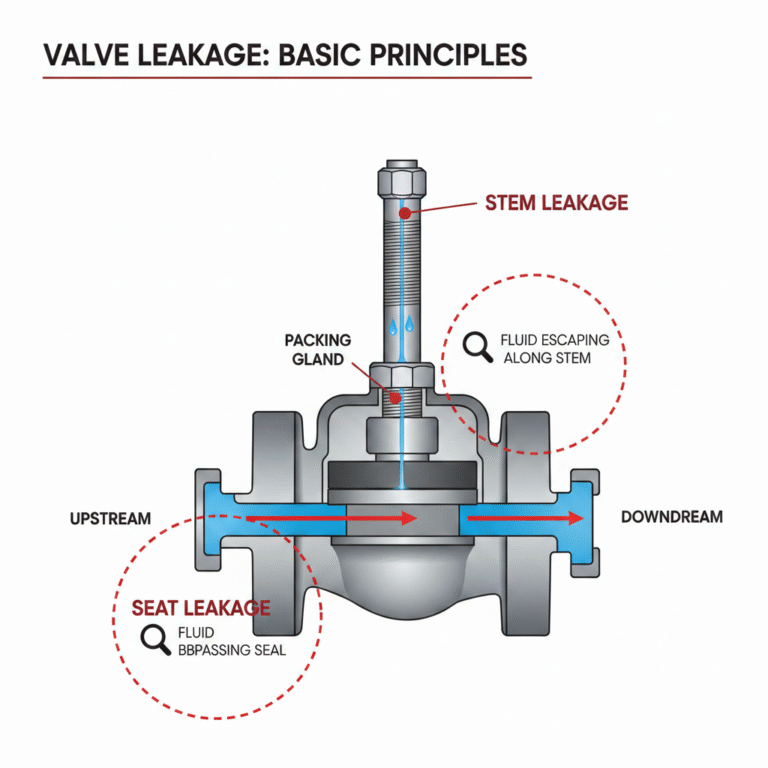
Valves operate by creating a seal between the valve plug (such as a valve disc, ball, or gate) and the valve seat, cutting off the fluid flow. Leakage typically occurs at two key locations:
Seat Leakage: This happens when the valve plug and seat do not make a perfect seal, allowing fluid to bypass the sealing surface from the upstream side to the downstream side. This is the primary form of leakage.
Stem Leakage: For valves with a movable stem (such as globe or gate valves), leakage occurs at the packing gland, where the sealing is imperfect, allowing fluid to leak along the stem.
2. Key Factors Affecting Valve Leakage
Leakage is not a fixed value; it is influenced by several factors related to both the valve design and operating conditions:
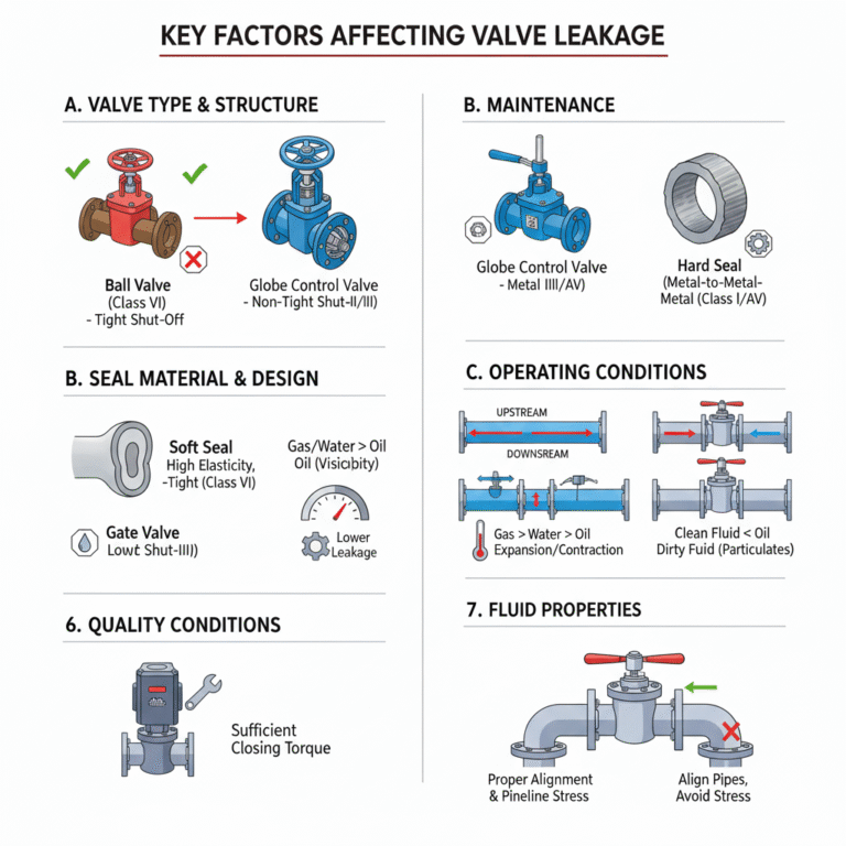
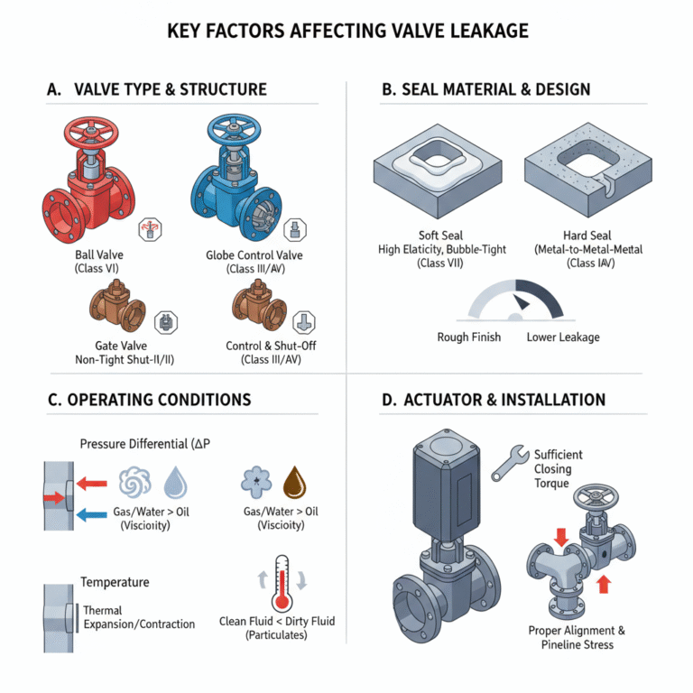
A. Valve Type and Structure
Shut-off Characteristics:
Tight shut-off: Ball valves, plug valves, most butterfly valves (except those with metal seals), and globe valves. These valves have a “face-to-face” or “line contact” sealing mechanism, ensuring zero or minimal leakage under normal conditions (meets ANSI/FCI 70-2 Class VI standards).
Both control and shut-off: Control valves (such as single-seated or cage-type valves) are designed to balance both control performance and shut-off. Their leakage class is usually Class IV or Class III, which allows more leakage than tight shut-off valves.
Non-tight shut-off: Gate valves, which have a “face-to-face” seal but are prone to erosion, and standard metal-sealed butterfly valves. These valves typically have lower leakage ratings (such as Class I or II) and allow a certain degree of leakage.
B. Seal Material and Design
Soft Seals vs. Hard Seals:
Soft seals (e.g., PTFE, rubber): These are highly elastic and can compensate for microscopic surface imperfections, providing excellent sealing performance (down to bubble-tight levels). However, they are not suitable for high temperatures or pressures.
Hard seals (e.g., metal-to-metal): These seals are resistant to high temperatures, pressure, and erosion. However, they require high closing forces and precise machining to achieve low leakage. Typically, they result in higher leakage than soft-seal valves.
Surface Finish and Machining Precision: The smoother and more precise the sealing surface (in terms of roundness and flatness), the lower the leakage rate.
C. Operating Conditions
Pressure Differential (ΔP): This is the most direct influence on leakage. Leakage is roughly proportional to the square root of the pressure differential (in turbulent flow conditions). The larger the pressure differential, the stronger the force pushing the fluid through microscopic gaps, leading to increased leakage.
Fluid Properties:
Viscosity: Low-viscosity fluids (such as water, steam, or gases) are more likely to leak through small gaps, resulting in higher leakage rates. Under identical conditions, gas leakage will generally be higher than liquid leakage.
Cleanliness: Fluids with particulates or crystallizing substances can erode, scratch, or obstruct the sealing surfaces, increasing leakage dramatically.
Temperature: Temperature changes cause materials to expand or contract, potentially altering the sealing gap and affecting leak tightness.
D. Actuator and Installation
Closing Torque/Force: The torque applied when closing the valve must be sufficient to overcome the pressure-induced forces and ensure that the seal is tight. Insufficient torque is a common cause of leakage.
Alignment and Pipeline Stress: Improper installation can cause valve body distortion, misalignment of the valve plug and seat, leading to leakage.
3. Standardization and Classification of Leakage Rates
International standards like ANSI/FCI 70-2 and IEC 60534-4 classify industrial valve leakage based on seat leakage, as shown below:
| Class | Description | Maximum Allowable Leakage (based on water) | Typical Applications |
|---|---|---|---|
| Class I | Not required to test; minimal leakage | – | Economical general-purpose valves |
| Class II | Used for double-seated valves | 0.5% of valve capacity (full open) | Double-seat control valves |
| Class III | Common for industrial shut-off valves | 0.1% of valve capacity | Standard industrial shut-off valves (e.g., some gate, globe valves) |
| Class IV | Metal-seated valves with bubble-tight seal | 0.01% of valve capacity or calculated (whichever is smaller) | High-performance metal-seated shut-off valves |
| Class V | Soft-sealed valves with “zero leakage” | Less than 0.04 mL per inch of diameter per minute (approx. 5-6 bubbles/min) | Critical soft-sealed shut-off valves (e.g., power station feedwater systems) |
| Class VI | Bubble-tight sealing for soft-sealed valves | Specific bubbles/minute based on valve diameter (tested at 50 psi or 3.5 bar) | Applications requiring absolute shut-off, such as food, pharmaceutical, and petrochemical industries |
Note: These leakage rates are based on tests with water or air. Actual leakage will vary with different media.
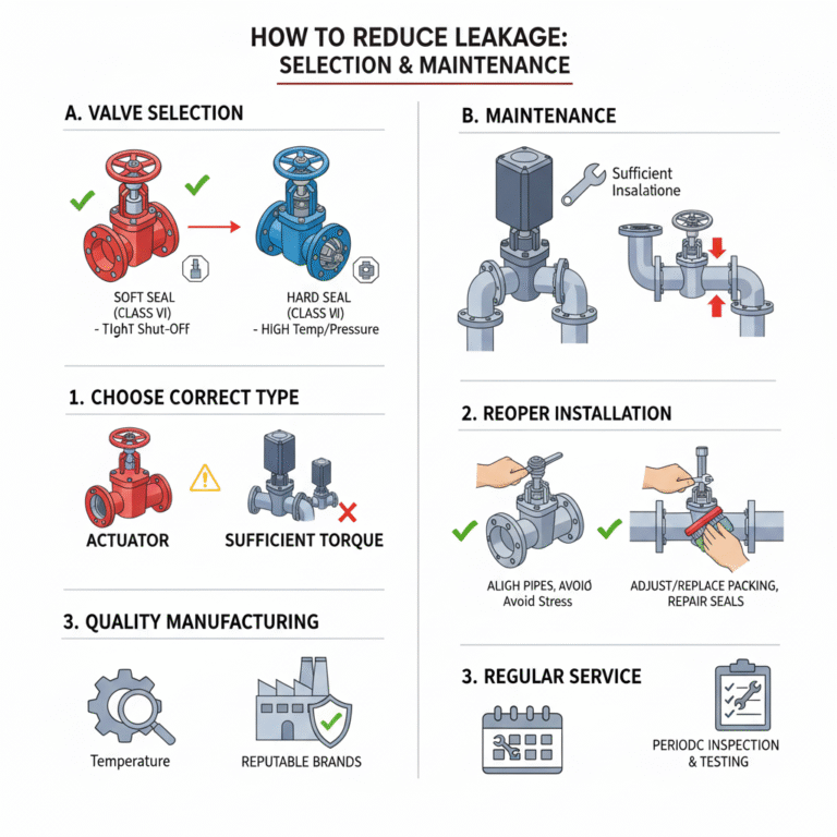
4. How to Reduce Leakage: Valve Selection and Maintenance Recommendations
Proper Valve Selection:
For applications requiring zero or minimal leakage (e.g., final shut-off, hazardous media), choose soft-sealed ball valves, plug valves, or high-performance butterfly valves (Class VI).
For high-temperature, high-pressure conditions, choose precisely machined hard-sealed valves, but expect higher leakage rates (e.g., Class IV).
Ensure actuators are sized for the maximum working pressure differential and can provide adequate closing torque.
Manufacturing Quality: Choose reputable brands to ensure machining precision and quality of sealing materials.
Proper Installation and Operation: Ensure correct pipe alignment to avoid stress; valves should be fully opened and closed to prevent erosion of sealing surfaces from long-term partial opening.
Regular Maintenance:
For stem packing leakage, adjust or replace packing as necessary.
For seat leakage, repair or replace the valve plug/seat assembly according to the valve design.
Implement a preventive maintenance plan with periodic leakage testing for critical valves.
Conclusion
The relationship between valves and leakage rates is dynamic and influenced by multiple factors. Ultimately, it is a balance between “sealing ability” and “operating conditions.” Properly designed, selected, and maintained valves can keep leakage within acceptable levels, ensuring safety, environmental protection, and economic efficiency throughout their service life.
In simple terms: The valve type determines leakage potential, the sealing material sets the base leakage level, pressure differential and fluid characteristics drive leakage, and correct selection and maintenance are crucial to controlling leakage.