1. Range and blind spot
The range and blind spot are two important indicators of the ultrasonic level meter.
The range represents the range that can be measured by this level meter. It is the sensitivity of the transducer that is reflected. In other words, the larger the range, the higher the sensitivity. Most manufacturers’ nominal ranges are for flat liquid levels, which means that when actually measuring, fluctuating levels, floating objects on the surface, measuring solid material levels, dust, and vapor, all may result in the range not reaching the nominal value. For example, if a 50m range device is used to measure corn, it can only actually measure up to 2 0m. The blind zone is an important indicator of how good the transducer is.
The blind zone also becomes the dead zone, a distance that the ultrasonic level meter cannot measure, it is caused by the aftershock of the ultrasonic transducer. For example, a blind zone of 3 0 c m means that when the distance between the liquid and the probe is less than 3 0 c m, there will be no measurement. For the same range, the smaller the blind spot, the better the design of the transducer. For closed tanks or short measuring ranges, the easier the installation will be. Therefore the blind spot becomes an important indicator of how well the transducer is doing for the same range.
2. Temperature and accuracy
The temperature range is mostly stated as -2 0 ~6 0℃. Because most of the level meters with LCD displays, the working temperature of the LCD screen can only be in this range, beyond this range, the LCD display will appear abnormal phenomenon. If the limits of the LCD are not taken into account, it is generally possible to achieve a range of -4 0 to 8 0°C. Piezoelectric ceramics have a Curie temperature of about 300 degrees. The Curie temperature is generally a safe temperature, so in general, it is difficult to operate an ultrasonic transducer above 150 degrees. When the temperature exceeds 150°C, it is easy to damage the piezoelectric ceramics inside. Therefore 150 degrees can be seen as an absolute destruction temperature. In addition, some of the materials used in the manufacturing process of ultrasonic transducers cannot be operated at temperatures above 1 0 0°C for long periods of time. The limit temperature for most transducers is 1 0 0°C.
The reason why accuracy and temperature are considered together is that in air, a temperature measurement error of 1°C has an effect on the speed of sound of 0.6m/S,20°C, and the speed of sound at 1 atmosphere is approximately 340m/S. It can therefore be calculated that the effect on the measurement error is 0.17%, which means that if the temperature measurement error is 3°C, the level measurement error will exceed the nominal range of 0.5% for most manufacturers. The actual 0.5% accuracy is therefore for ambient temperature and pressure. For both high and low temperatures, it is possible that the measurement accuracy will exceed 0.5%. Where there are temperature gradients and rapid changes in temperature, the measurement error will also increase as a result. Another influence on measurement accuracy is gas composition. This means that in the case of volatile liquids, the volatilization of the liquid causes a change in the air composition, which in turn causes a change in the sound velocity of the gas, resulting in a measurement error.
3. Pressure
In the case of negative pressure, ultrasonic measurement is generally not recommended because ultrasonic propagation is achieved through the gas. Negative pressure means that the air inside is thin, and ultrasound propagates under thin air, one is that the speed of sound will change, causing measurement errors, and the other is that inside thin air, the attenuation of sound waves increases, resulting in a reduced measurement range or even the inability to measure. Positive pressure is mainly the impact of the probe structure, as long as the probe structure is not a problem. Will not cause an air leakage phenomenon. Then in the case of large pressure ultrasonic level meter is able to work.
4. Corrosive
The main test of the level meter’s corrosiveness is the material of the probe. In a weak acidic and alkaline environment, ordinary plastic housing will do. Housing made of PTFE will resist most strong acids and bases.
The point to note here is that if the measured substance is relatively corrosive and volatile, then it is best to glue peak the circuit board when using an all-in-one level meter. This is because most of the housings that can be waterproof are not gas-proof. The gas will look down on the circuit board when it gets inside the all-in-one device.
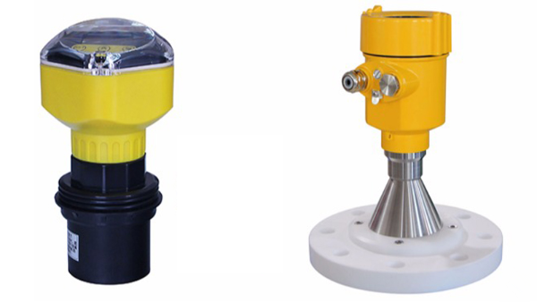
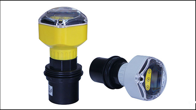
5. Directionality and mounting structure
Mounting configurations are generally available in the flange and threaded mounting. Lifting is not recommended. This is because lifting is susceptible to the effects of wind. However, when mounting, the effect of the blind zone is generally taken into account. We have to physically ensure that the distance from the highest liquid level to the probe surface is greater than the blind zone. In order to avoid the blind zone, when installing with an extended conduit, it must be noted that the angle formed between the ends of the radiating surface of the probe and the ends of the end face of the conduit must be greater than the acute angle of the transducer. (Sharp angle: the angle between the first minimal value appearing on both sides of the beam) Most transducers for level meters can be seen as circular piston arrays. Then the angle of the acute angle can be calculated by the following formula: Formula for calculating the acute angle of the transducer: θ = 2arcsin(0.61λ/a). The product nominal is the half power angle of the general transducer. The formula for the half-power angle is θ-3dB = 2arcsin(0.26λ/a). This verifies that the manufacturer’s nominal beam angle is true. The smaller the beam angle the better, because for large ranges the beam angle is too small, then it is more difficult to align vertically with the liquid surface.
λ = wavelength = speed of sound/frequency
a = radius, which is the radius of the radiating surface of the transducer
6. Power supply and signal output
The power supply is generally AC power supply 9 5 ~ 2 3 0 VAC, 24VDC four-wire system, 2 4VDC two-wire system three. Output methods are display interface, current 4 ~ 20Ma, voltage 1-5V, communication mode 4 8 5 communication, Hart communication, GPRS communication, etc.