1. Introduction
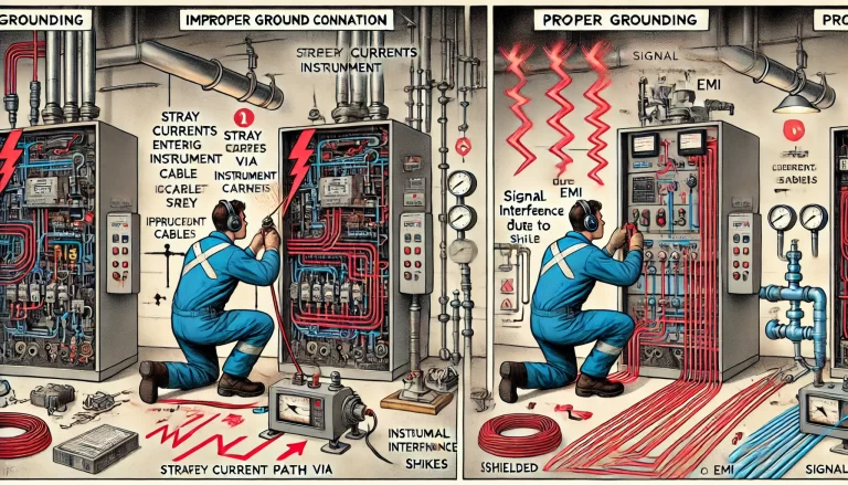
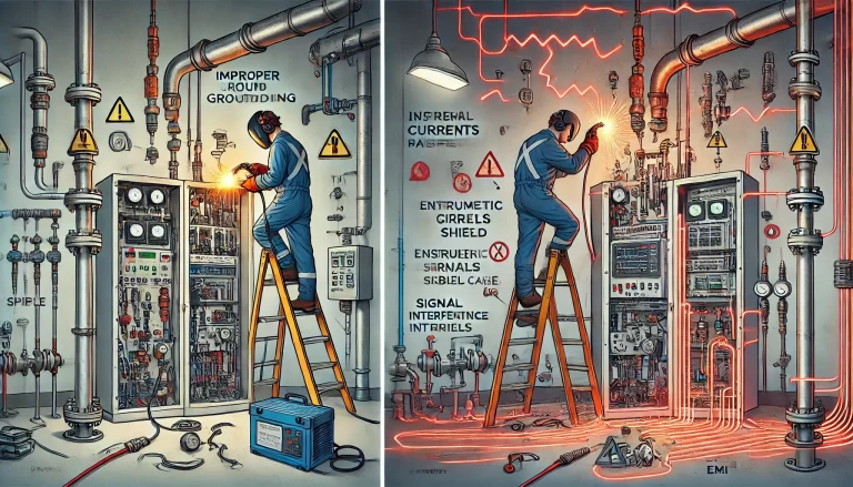
Improper grounding during welding operations poses serious threats to the performance and integrity of industrial automation and instrumentation systems. Through electromagnetic interference (EMI), ground potential differences, and stray currents, welding can cause signal distortion, equipment damage, and even control system malfunctions.
This article explores the core risks, real-world examples, and preventive measures, followed by a detailed guide on standardized grounding practices for control instrumentation.
2. Core Impacts of Improper Grounding During Welding
2.1 Signal Interference
Mechanism: Improper grounding creates unintended current loops that can generate electromagnetic pulses or harmonic noise. These interfere with low-level instrumentation signals (e.g., 4–20 mA current loops, mV voltage signals).
Effect: This interference may cause signal fluctuation, distortion, or false readings.
Example: During arc welding, high-frequency noise may couple into signal cables, causing DCS readings to spike or drop erratically.
2.2 Equipment Damage
Ground Potential Difference (GPD): If welding equipment and instrumentation systems are not on a common ground, a potential difference of several hundred volts can arise, damaging circuit boards, isolators, or I/O cards in PLC/DCS.
Stray Current Corrosion: Uncontrolled ground paths can channel welding currents through instrument enclosures or terminals, accelerating internal electrochemical corrosion and reducing equipment lifespan.
2.3 System Malfunctions
Control Logic Interference: Electromagnetic disturbance may lead to logic controller (PLC, DCS) mis-triggering interlocks or unintentional actuation of final control elements like solenoid or control valves.
Safety Risks: In severe cases, this could result in process disruptions or unsafe operating conditions.
3. Common Risk Scenarios
Scenario 1:
Welding is conducted near instrumentation cables without independent grounding. The welding return current couples through the soil into the instrument grounding system, causing abnormal readings in temperature transmitters.
Scenario 2:
A process pipeline (connected to field instruments) is used as the welding return path. Large welding currents induce voltages along the pipeline, damaging diaphragm seals or sensitive electronics in pressure transmitters.
4. Preventive Measures
| Measure | Description |
|---|---|
| 4.1 Independent Grounding for Welding | Install a separate ground rod for welding operations, at least 5 meters away from the instrument grounding system. |
| 4.2 Signal Isolation | Use galvanic isolators or signal isolator modules to break potential paths for interference. |
| 4.3 Cable Shielding & Routing | Use shielded signal cables, grounded at one end only. Avoid routing instrument cables near welding zones. |
| 4.4 Temporary Disconnection | Where feasible, disconnect power to critical instruments or bypass them during welding, with a risk assessment for process safety. |
5. Instrumentation Grounding Standards and Practices
5.1 Grounding Types
| Type | Description |
|---|---|
| Protective Grounding | All non-current-carrying metal parts (e.g., panels, enclosures) must be grounded for personnel safety. Instruments powered below 36V may be exempt unless exposed to higher voltages. |
| Functional (Working) Grounding | Refers to grounding of signal circuits and cable shields. Isolated signals may be left ungrounded; non-isolated signals should be grounded at a single point, usually at the power supply negative terminal. |
| Intrinsic Safety (IS) Grounding |
Zener Barriers require proper IS grounding;
Isolated Barriers usually do not require special grounding.
Zener IS ground must be bonded to the signal reference ground. | | Antistatic Grounding | Control room floors, workbenches, and operator desks should be grounded to prevent static buildup. If protective and functional grounds are implemented, additional static grounding is not needed. | | Lightning Protection Grounding | Where field signal lines enter buildings, a lightning protection system must be implemented. Instrument lightning grounds should share a common system with electrical lightning protection but not with independent lightning rods.
5.2 Grounding Methodology
| Aspect | Standard Practice |
|---|---|
| Preferred Method | Equipotential Single-Point Grounding (SPG), integrated into a facility-wide grounding network. |
| Alternative | In absence of equipotential bonding, allow isolated single-point grounding for instrumentation and connect protective grounding to electrical ground. |
| Minimum Distance Requirements |
Instrument vs welding ground: ≥5 m
Instrument vs high-voltage equipment or surge protectors: ≥5 m
Instrument vs independent lightning rods: ≥20 m
5.3 Grounding Connection Specifications
| Component | Specification |
|---|---|
| Grounding Wires | Multi-stranded copper insulated wire or shielded cable. |
| Ground Busbar | Copper bar with cross-section ≥25 mm × 6 mm. |
| Ground Plate | Copper plate ≥6 mm thick. |
| Ground Resistance |
Equipment Ground Resistance: ≤4 Ω
Grounding Lead Resistance (connection to earth): ≤1 Ω
5.4 Additional Notes
Signal cable shields should be grounded at only one end to avoid ground loops.
If the signal source is grounded, the shield should be grounded at the source end; otherwise, ground it at the receiving instrument end.
Metallic trays and conduits must be bonded to ground. If welded directly, do not connect to flammable substance pipelines.
6. Conclusion
Improper grounding during welding can lead to both functional disruption and permanent damage of automation instrumentation due to electromagnetic interference, GPD, and stray currents. Effective risk control requires:
Proper design of separate grounding systems,
Implementation of physical isolation and shielding measures,
Compliance with grounding classification and connection standards.
By ensuring rigorous grounding discipline, instrumentation reliability and system safety can be significantly enhanced during welding and other high-current operations.