The differential pressure flow meter, also known as the throttling flow meter, is the most mature and commonly used flow measurement instrument in industrial production. It is based on the principle of fluid throttling, utilizing the pressure difference generated when the fluid passes through the throttling device to achieve flow measurement. It is widely used in the subsidiary company’s production process for measuring steam, water, air, and other media.
1. Composition of a Differential Pressure Flow Meter:
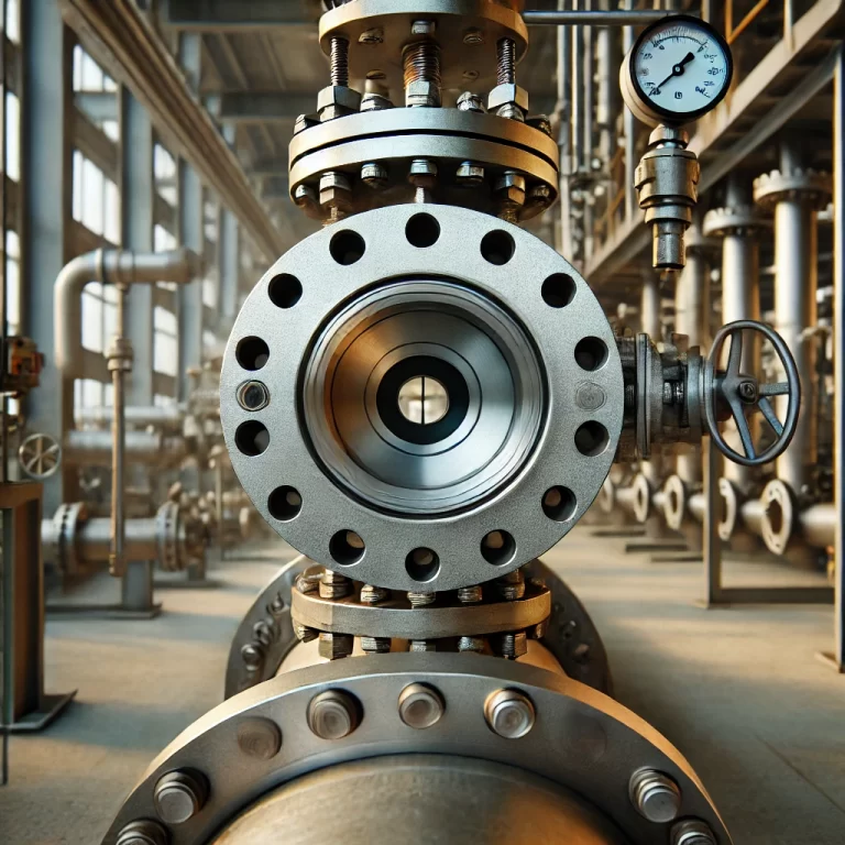
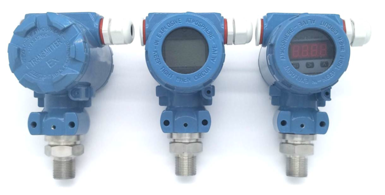
A differential pressure flow meter generally consists of a throttling device (such as a standard orifice plate, nozzle, bend tube, vortex, etc.), pressure guiding tubes, a three-valve manifold, a differential pressure transmitter, a primary valve, and a drain valve.
2. Working Principle of a Differential Pressure Flow Meter:
When fluid flows through a pipeline equipped with a throttling device, the phenomenon where the static pressure of the fluid changes on the walls before and after the throttling device is known as the throttling effect. The throttling device is a locally constricted element placed within the pipeline. As the fluid flows through the pipeline, it possesses both static pressure energy due to the pressure and kinetic energy due to its velocity. Under certain conditions, these two forms of energy can transform into each other, while the total amount of energy involved in the transformation remains constant.
When a continuously flowing fluid encounters a throttling device installed in the pipeline, the fluid is obstructed by the device, causing local constriction of the flow stream. As a result, the flow area decreases, the flow velocity increases, and thus the kinetic energy also increases. Due to the principle of energy conservation, the static pressure inevitably decreases. Because of inertia, the point of maximum contraction of the flow stream does not occur at the orifice of the throttling device but at a certain point downstream. At this point, the flow velocity is the highest, and the corresponding static pressure is the lowest.
In other words, when the fluid flows through the throttling device, a pressure difference is generated before and after the device. The fluid pressure before the throttling device is higher and is referred to as positive pressure, denoted by “+”, while the pressure after the throttling device is lower and is referred to as negative pressure, denoted by “-”. The size of the pressure difference before and after the throttling device is related to the flow rate. The larger the flow rate of the fluid in the pipeline, the greater the pressure difference generated across the throttling device. By measuring the pressure difference before and after the throttling device, the flow rate in the pipeline can be determined. This is the basic principle behind measuring flow with a throttling device.
3. Fault Diagnosis and Handling of Differential Pressure Flow Meters:
1. Causes of Instrument Faults:
The main sources of instrument faults can be divided into two categories:
- Process-related causes.
- Instrument-related causes.
Instrument-related causes can be further divided into issues with the instrument itself and issues with auxiliary components. The instrument itself includes the flow meter, transmitter, temperature measurement elements, and display instruments. Auxiliary components include valves, pressure guiding tubes, tanks, connectors, and insulation for heating systems. Most faults are often caused by auxiliary components.
The typical order of fault diagnosis is to start by checking the process, then the instrument. First, gather detailed information from the process operators about the conditions under which the fault occurred, and inspect the on-site process flow, media conditions (temperature, pressure), valve positions, and pump operation. In some cases, changes in the process might cause abnormalities that the operators are unaware of, leading them to mistakenly assume the fault lies with the instrument. If instrument maintenance personnel proceed with dismantling and inspecting the instrument system without fully understanding the fault’s cause, it could not only fail to resolve the issue but also worsen the problem or complicate its resolution.
For example:
- Process load changes, but operators analyze based on prior experience, possibly misinterpreting correct flow values as being erroneous.
- The actual flow in the pipeline may be so small that it falls within the flow meter’s dead zone, so the lack of display is normal but may be mistaken for a fault.
- Even if a pipeline valve is closed, leakage inside the valve might result in some flow, which can be misinterpreted as the instrument running empty.
- Long-distance steam transmission or poor pipeline insulation can cause dry saturated steam passing through the flow meter to turn into wet saturated steam. Using pressure and temperature to estimate density in such cases introduces errors, and condensed steam may be discharged through a trap, further causing measurement discrepancies.
In summary, process-related causes leading to changes in flow conditions can be complex and varied. In these cases, careful inspection is essential, and sometimes waiting and observing until the process returns to normal can cause the instrument “fault” to disappear.
Faults Caused by Instrument-Related Issues and Their Handling:
If the process system is confirmed to be operating normally, then the next step is to inspect the instrument system. The causes of faults in the instrument system can be divided into two categories: issues with the instrument itself and issues with auxiliary components. In terms of fault frequency, auxiliary component issues occur more often than problems with the instrument itself, so they should be the primary focus of the inspection. There is no fixed sequence for checking faults; the general approach is to make an initial diagnosis based on the fault symptoms and then proceed with troubleshooting.
1. Flow in the Pipeline, but No Output from the Instrument:
This type of fault is relatively easy to diagnose. The first step is to check whether the transmitter’s power supply is normal. If the power supply is normal, measure whether there is any current output (it should be greater than 4mA). If there is current output, it indicates that the fault is not in the transmitter, and the display section of the instrument should be checked. If there is no current output or if the current is less than or equal to 4mA, further inspection of the transmitter is necessary. For currents lower than 4mA, the issue could be due to a significantly low zero point, resulting in no output at low flow rates. This can be resolved by recalibrating the zero point. For situations where there is no current output or the current is less than or equal to 2mA, the transmitter may be faulty.
For smart transmitters, if there is a fault in the instrument itself, there is usually an error code displayed (if the display is absent, it can be checked using a handheld communicator). The error code can be used to identify the cause of the fault. Once the instrument is confirmed to be functioning correctly, the next step is to inspect the auxiliary components. One common cause of issues is a leakage in the balance valve of the three-valve manifold, which can cause pressure equalization in the high and low-pressure chambers of the transmitter, leading to no output.
In most cases, balance valve leaks are difficult to detect. Here is a simple method to roughly diagnose the problem: First, close the positive and negative valves of the three-valve manifold, then open the balance valve and wait for the transmitter output to drop to zero before closing it. Afterward, open the positive valve and check whether the transmitter output rises quickly. If the output rises slowly or does not reach the maximum value, it indicates a severe leak in the balance valve.
There may also be leaks in the positive (high-pressure) side of the pressure guiding tube. Inspection points include the root and valve on the positive side, the tank, each connector, the three-valve manifold, the transmitter’s drain cock (check if it is tightly closed), and whether the drain or vent valve is leaking or not fully closed. Each part should be thoroughly checked for leaks. For instruments with a display head, the display can indicate whether the zero point is drifting. For those without a display head, the overall symptom is no output (the actual current is below 4mA). This issue is particularly common in low differential pressure ranges or when the flow is low, where even a small leak in the positive pressure guiding section can result in no output.
There may also be blockages in the positive (high-pressure) side of the pressure guiding tube (including valves and tanks). Initially, when the blockage occurs, the pressure trapped in that section of the tube can be maintained, and no immediate output loss may occur. However, once the pipeline pressure changes, the pressure variation cannot be transmitted promptly to the high-pressure side of the transmitter, leading to an uncertain effect on the transmitter’s output. In some cases, it may even cause the negative pressure to exceed the positive pressure, resulting in a zero or negative output.
Diagnosis Method: Open the drain or vent valve and assess the discharge flow and pressure. Based on the flow’s ease of passage or the discharge pressure, you can determine if there is a blockage. In most cases, opening the drain or vent will resolve the blockage issue.
2. No Flow in the Pipeline but Instrument Shows Output:
First, check if the issue is caused by an incorrect zero setting in the transmitter. The main reasons for an incorrect zero setting are: (1) the transmitter’s zero point is too high, and (2) the small signal cutoff is not set or is set too low. To fix a high zero point, recalibrate the zero point. For the second issue, the solution is to adjust the small signal cutoff appropriately.
If there is a leak in the negative pressure guiding tube, even when there is no flow in the pipeline, the pressure in the positive pressure guiding tube will be higher than that in the negative pressure tube. This creates an additional differential pressure on the transmitter, resulting in a flow output. The inspection method and points for leaks are the same as mentioned earlier.
For vacuum process pipelines, if there is a leak in the positive pressure guiding tube, the transmitter may still show an output even when there is no flow. However, detecting leaks online can be difficult.
If there is a blockage in the negative pressure guiding tube, the analysis is similar to the previous case. When pipeline pressure changes (even without flow), if the pressure changes in the positive and negative tubes are not synchronized, this may cause the positive pressure to exceed the negative pressure, resulting in an output from the transmitter. This can be handled by draining the system.
For situations where there is no flow but the instrument shows output, if the cause is unclear, try draining all the media from both the positive and negative pressure guiding tubes. Then, restart the instrument following the earlier described method, and recalibrate the system’s zero point. Sometimes, this can resolve the issue, especially in cases where the liquid contains gas or the gas contains liquid.
3. Unstable Flow Signal:
This type of fault is mostly caused by issues with the pressure guiding tubes or other auxiliary components, while faults with the instrument itself are rare. Therefore, the focus should first be on inspecting the auxiliary components. The instability is often due to gas trapped in the pressure guiding tubes or the transmitter’s measurement chamber when measuring liquids and steam, or liquid when measuring gases.
Solution: Open the lower (or upper) drain (or vent) valve of the tubes to release any trapped gas or liquid. Also, open the drain/vent cock on the transmitter to discharge any gas or liquid. In most cases, this resolves the issue. (Note: take caution when handling systems with isolation fluids or hazardous media, as described earlier.)
If the pipeline is equipped with heating, excessive heating may cause irregular fluctuations in output due to localized vaporization of the liquid inside the pressure guiding tubes. This has been observed in cases where heating was still active during summer. Since the insulation layer makes it difficult to detect, a temporary shutdown of the heat source can be attempted to see if the fluctuations decrease or disappear. However, care should be taken during colder seasons to avoid freezing by not turning off the heat for too long. Alternatively, reducing the heating valve’s opening for a short time can help determine the cause.
Another possible cause is insufficient heating, leading to partial freezing of the pressure guiding tubes, which can disrupt the pressure signal transmission and cause flow fluctuations. This can be resolved by checking the heating valve’s opening and adjusting the heat source as needed.
If there are impurities or debris in the pressure guiding tubes, it can create a partial blockage that hinders the transmission of the differential pressure signal, resulting in irregular output fluctuations. This can also be solved by draining the system.
Additionally, if the transmitter’s terminal connections are loose or the wiring has poor contact, the signal can intermittently drop out. Reconnecting the wires securely should resolve this issue.
4. For Possible Issues with the Flow Meter, the Analysis and Troubleshooting Should Focus on the Following Aspects:
Leak in the Pressure Guiding Tubes:
- A leak in the positive pressure side will cause a low reading; a small leak in the balance valve will also result in low readings.
- Solution: Carefully inspect all components in the pipeline (including valves, connectors, drain, and vent valves) for leaks.
Uneven Heating of Positive and Negative Pressure Guiding Tubes:
- This can cause condensation in the tubes to have different densities, resulting in measurement errors (which can be significant). If the positive side is overheated, the instrument will show low readings; if the negative side is overheated, the readings will be high.
- Solution: Rebalance the heating insulation or adjust the heating to ensure that both the positive and negative pressure tubes are at the same temperature, and that the condensation liquid inside the tubes has the same temperature.
Presence of Non-Measured Media in the Pressure Guiding Tubes or Transmitter Chamber:
- This can cause unequal static pressure in the tubes, resulting in additional errors and incorrect measurements.
- Solution: Drain the pressure guiding tubes and the transmitter, then restart the instrument.
Blockage in the Positive or Negative Pressure Guiding Tubes:
- If the real differential pressure signal cannot be transmitted to the transmitter promptly, it will cause a fixed or delayed output, leading to errors.
- Solution: Use the drain method to clear the blockage.
Unequal Liquid Levels in Systems with Isolation Fluids:
- This can result in unequal static pressures in the positive and negative tubes, causing additional errors.
- Solution: Check and confirm the liquid levels, and refill the isolation fluids if necessary.
Incorrect Zero Calibration or Long-Term Zero Drift:
- If the zero point of the transmitter or system has drifted, it will affect measurements across the entire range.
- Solution: Perform proper system or transmitter zero calibration.
Small Valve Opening in the Positive or Negative Root Valves:
- If one of the root valves is not fully open, it can distort or delay the transmission of the differential pressure, causing measurement errors.
- Solution: Ensure both valves are opened equally.
Repeating Square Root Calculation in the Transmitter and Display Instrument:
- Many modern display instruments or DCS systems are configured with a fixed square root model for differential pressure flow meters, requiring the transmitter to output linearly. If the transmitter is incorrectly set to output after performing the square root calculation, it will result in significant errors.
- Solution: Set the transmitter to linear output.
Improper Small Signal Cutoff Settings:
- Both the transmitter and display instruments have a small signal cutoff feature. If the cutoff is set too high, it may cause loss of flow data. If set too low, it may accumulate interference signals as flow data, causing cumulative errors.
- Solution: Set the small signal cutoff value appropriately.
Inconsistent Settings between Display Instruments and Transmitters:
- Discrepancies between the settings of the transmitter (e.g., range, temperature, and pressure compensation) and the display instrument can result in errors. For example, if the differential pressure range of the transmitter is changed but the display instrument’s settings are not updated, it will cause errors.
- Solution: Ensure that the settings of the display instrument match those of the transmitter.
- Errors Due to Incorrect Density:
- Differential pressure flow meters, like most flow meters, measure the volumetric flow rate under operating conditions. For trade calculations and display purposes, the mass flow rate or standard volumetric flow rate is calculated using density. If the density is incorrect, flow measurement errors will occur. Common causes of density inaccuracies include:
- a. No Compensation for the Measurement System: The actual operating conditions deviate significantly from the design state.
- b. Large Errors in Compensation Instruments: Errors caused by pressure and temperature, as mentioned earlier.
- c. Incorrect Steam Density Compensation: Using the ideal gas equation instead of specific formulas or steam density tables.
- Significant Errors When Using Different Types of Flow Meters to Measure the Same Flow:
- It is common for large discrepancies to occur between different types of flow meters when measuring the same flow, although the readings may sometimes be accurate. For example, when steam flow is at 6t/h, vortex and annular flow meters may measure accurately, but pitot tubes and elbow meters may fail to measure properly as the steam velocity has fallen below their measurable limit (resulting in flow loss). If such meters are compared to a V-cone flow meter, there will definitely be discrepancies, especially over extended periods of low flow.
- Solution: This explains why multiple flow meters installed in the same pipeline, even when functioning correctly, may occasionally show large measurement discrepancies.
- Measurement Errors in Intermittent Steam Usage:
- If the transmitter is installed above the flow meter and the “rear pressure tapping” structure is used, measurement errors may occur due to liquid accumulation in the pipeline or improper installation.
- Solution: Switch to a flow meter with a “wall pressure tapping” structure and follow proper installation guidelines to correct the issue.
This detailed approach should help identify and resolve issues related to differential pressure flow meters.