1. Thermal resistance thermometer

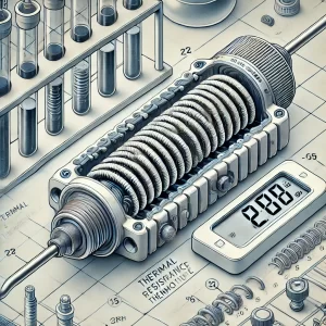
Common faults of industrial thermal resistors are open circuit and short circuit. Generally, open circuit is more common, which is caused by the thin wire of thermal resistor.
Open circuit and short circuit are easy to judge. You can use the “×1Ω” position of the multimeter. If the measured resistance is less than R0, there may be a short circuit; if the multimeter indicates infinity, it can be determined that the resistor body is open circuit. Resistor body short circuit is generally easier to handle.
As long as it does not affect the length and thickness of the resistor wire, find the short circuit and blow it dry, and strengthen the insulation.
The repair of resistor body open circuit must change the length of the resistor wire and affect the resistance value. For this reason, it is better to replace the resistor body with a new one. If welding is used for repair, it must be calibrated and qualified before use.
2. Thermocouple Thermometer
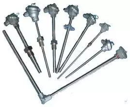
The correct use of thermocouples can not only accurately obtain the temperature value and ensure the product quality, but also save the material consumption of thermocouples, saving money and ensuring product quality. In addition to the common errors caused by reverse connection, wrong use and loose connection of compensation wires (treatment method: correctly use compensation wires and tighten the terminal blocks), incorrect installation, thermal conductivity and time lag errors are the main errors in the use of thermocouples.

1. Errors introduced by improper installation
For example, the installation position and insertion depth of the thermocouple cannot reflect the actual temperature of the furnace. In other words, the thermocouple should not be installed too close to the door and heating place, and the insertion depth should be at least 8 to 10 times the diameter of the protection tube; the gap between the thermocouple protection sleeve and the wall is not filled with insulating material, which causes heat overflow or cold air intrusion in the furnace.
Therefore, the gap between the thermocouple protection tube and the furnace wall hole should be blocked with insulating materials such as refractory mud or asbestos rope to prevent hot and cold air convection from affecting the accuracy of temperature measurement; the cold end of the thermocouple is too close to the furnace body, causing the temperature to exceed 100°C; the installation of thermocouples should avoid strong magnetic fields and strong electric fields as much as possible, so the thermocouple and power cable should not be installed in the same conduit to avoid introducing interference and causing errors; the thermocouple cannot be installed in an area where the measured medium rarely flows.
When using a thermocouple to measure the gas temperature in the tube, the thermocouple must be installed against the flow direction and in full contact with the gas.
2. Errors caused by insulation degradation
If the thermocouple is insulated, or there is too much dirt or salt residue on the protective tube and the wire drawing plate, the insulation between the thermocouple poles and the furnace wall will be poor, which is more serious at high temperatures. This will not only cause the loss of thermoelectric potential but also introduce interference. The error caused by this can sometimes reach hundreds of degrees.
3. Errors introduced by thermal inertia
Due to the thermal inertia of the thermocouple, the indicated value of the instrument lags behind the change of the measured temperature. This effect is particularly prominent when performing rapid measurements.
Therefore, thermocouples with thinner thermocouples and smaller protective tube diameters should be used as much as possible. When the temperature measurement environment permits, the protective tube can even be removed.
Due to the measurement lag, the amplitude of the temperature fluctuation detected by the thermocouple is smaller than the amplitude of the furnace temperature fluctuation.
The greater the measurement lag, the smaller the amplitude of the thermocouple fluctuation, and the greater the difference with the actual furnace temperature.
When using a thermocouple with a large time constant to measure or control temperature, although the temperature displayed by the instrument fluctuates very little, the actual furnace temperature may fluctuate greatly. In order to accurately measure the temperature, a thermocouple with a small time constant should be selected.
The time constant is inversely proportional to the heat transfer coefficient and is proportional to the diameter of the hot end of the thermocouple, the density of the material and the specific heat.
If you want to reduce the time constant, in addition to increasing the heat transfer coefficient, the most effective way is to minimize the size of the hot end.
In use, materials with good thermal conductivity, thin walls and small inner diameter protective sleeves are usually used. In more precise temperature measurements, bare wire thermocouples without protective sheaths are used, but thermocouples are easily damaged and should be calibrated and replaced in a timely manner.
4. Thermal resistance error
At high temperatures, if there is a layer of soot on the protection tube, dust will adhere to it, and the thermal resistance will increase, hindering the conduction of heat. At this time, the temperature indication is lower than the true value of the measured temperature. Therefore, the outside of the thermocouple protection tube should be kept clean to reduce the error.
3. Bimetallic thermometer
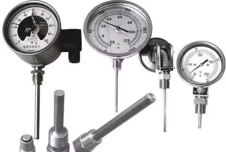
The working principle of the bimetallic thermometer is to use two metals with different temperature expansion coefficients. One end is welded at a fixed point, and the other end is distorted when the temperature changes, which is converted into a pointer deflection angle to indicate the temperature.
If a linear error occurs during use, the problem of inaccurate temperature indication can be adjusted by adjusting the pointer knob behind the thermometer. The adjusted thermometer can be used only after passing the calibration.

4. Pressure thermometer
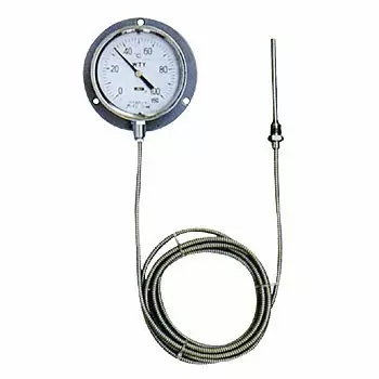
The pressure thermometer uses the thermal expansion and contraction of liquid to measure temperature. The closed system composed of the temperature bulb, capillary tube and spring tube is filled with the temperature measuring medium – liquid.
When the temperature bulb senses the temperature change, the pressure in the closed system changes due to the change in liquid volume, causing the curvature of the spring tube to change and displace its free end.
The pointer is then driven to rotate through the connecting rod and transmission mechanism, indicating the measured temperature on the dial. This instrument has the characteristics of linear scale, small temperature bulb volume, fast response speed, high sensitivity, and intuitive reading.
Common failures of commonly used pressure thermometers are that the pointer does not move and the indication deviation is large. If the pointer is stuck, you can use a needle puller to pull out the pointer, re-position the needle and calibrate it before using it again.

1. Common faults
Temperature control instruments are instruments that control the measured object through thermal resistors or thermocouples. The common faults are as follows:
· Improper installation position prevents the medium from fully exchanging heat with the measuring element, resulting in low indication;
· Poor insulation of the temperature measuring point causes rapid local heat dissipation, causing the temperature measuring point to be lower than the system temperature;
· Loose wiring and poor contact cause inaccurate indication. The thermal resistor is high and the thermocouple is low;
· Short circuit fault. The thermal resistor is low or minimum, and the thermocouple is low or faulty;
· Open circuit (open circuit) fault. The thermal resistor indicates the maximum, and the thermocouple has no indication or the minimum.
In addition, when analyzing the faults of the temperature control instrument system, it should be noted that most of the system instruments use electric instruments for measurement, indication and control, and the measurement lag is large.
2. Common fault analysis methods
1) First check the indication value of the temperature instrument system. If the indication value changes to the maximum or minimum, it can be determined that the instrument system is faulty.
The reason is that the temperature instrument system measurement generally has a large hysteresis, and sudden changes will not occur. The failure of the temperature control instrument is caused by the breakage of the thermocouple, thermal resistor and compensation wire, and the failure of the transmitter amplifier.
2) Check whether the indication value of the temperature control instrument system is constantly oscillating rapidly. This phenomenon is generally caused by improper adjustment of the control parameter PID.
3) Check whether the indication value of the temperature control instrument system fluctuates greatly and slowly. This phenomenon is generally caused by changes in process operation. If there is no change in process operation, it can be determined that the instrument control system itself has a fault.
4) After determining that the temperature control system itself is faulty, first check the instrument’s control valve input signal to see if there is any change.
If the input signal has not changed and the control valve has been activated, it can be determined that the control valve diaphragm has a leakage fault; check the control valve positioner input signal.
If the input signal has not changed and the output signal is changing, it is determined that the instrument’s positioner has a fault; check the instrument’s positioner input signal and the instrument’s regulator output signal.
If the regulator input signal has not changed and the output signal is changing, it can be determined that the instrument’s regulator itself has a fault.
