The target type flow switch, also known as a paddle flow switch, is a mechanical flow-sensing device composed of a target plate, sensing mechanism, and signal processing unit. It is widely used in industrial automation, water treatment systems, HVAC (Heating, Ventilation, and Air Conditioning), and refrigeration systems.
2. Working Principle
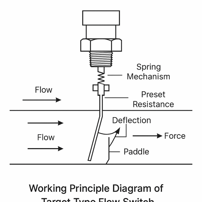
The design is based on the mechanical principle of force equilibrium. A circular or rectangular metal paddle (target plate) is vertically installed inside the pipeline. As the fluid flows through the pipe, it exerts force on the paddle, causing it to deflect.
The deflection force is proportional to the square of the fluid velocity.
A spring mechanism on the opposite end of the paddle provides preset resistance.
When the fluid flow exceeds the preset value, the force overcomes the spring tension and triggers a switch (mechanical or electronic), generating an on/off signal.
Figure 1: Working Principle Diagram of Target Type Flow Switch
3. Key Features
✅ Advantages:
Strong Anti-Interference Capability: Mechanical sensing is immune to bubbles, vibrations, temperature fluctuations, and pressure changes.
Wide Applicability: Suitable for liquids, gases, and media containing small solid particles.
Simple Structure: Compact design, easy to install, and low maintenance cost.
⚠️ Limitations:
Pressure Loss: The paddle introduces resistance to the flow, making it unsuitable for low-pressure or ultra-low flow applications.
Limited Accuracy: As a mechanical device, it generally has lower accuracy than electronic flow meters.
4. Installation Guidelines
⚙️ Installation Position:
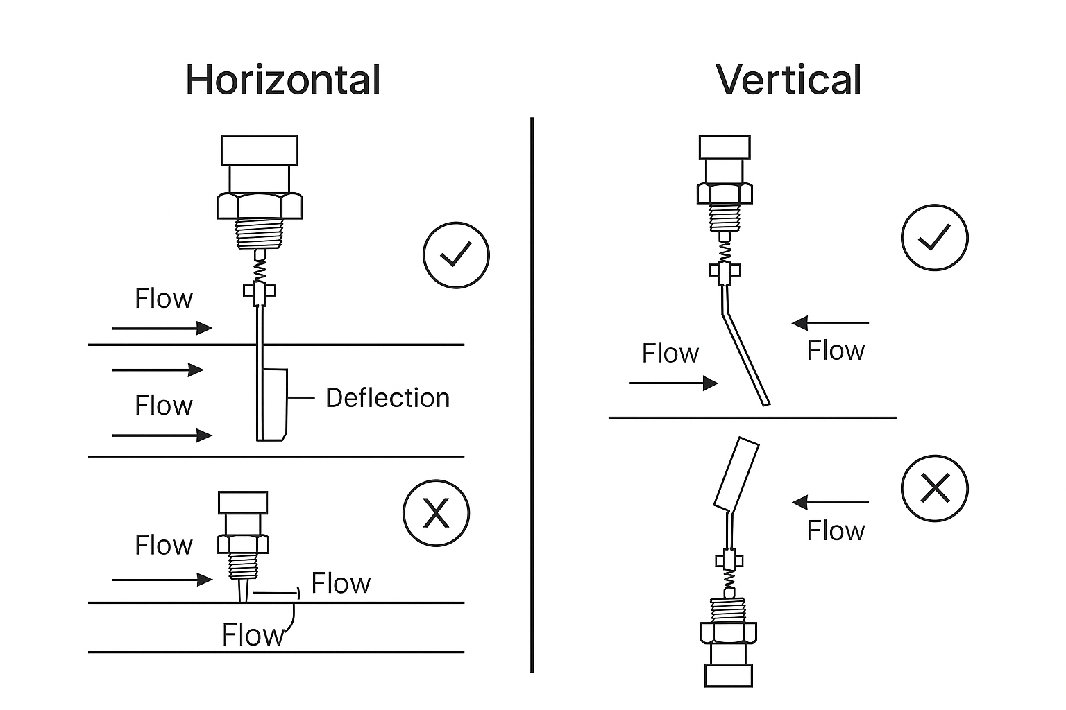
Preferred Orientation: Horizontal pipe installation is recommended.
Vertical Installation: If necessary, ensure that the fluid flows from bottom to top to counteract gravity.
Media with Particles: Avoid vertical installation when measuring fluids containing solid particles to prevent accumulation and clogging near the paddle.
Figure 2: Recommended Installation Orientation for Horizontal and Vertical Pipelines
🔧 Installation Requirements:
Straight Pipe Sections:
Minimum 5×D (upstream), 3×D (downstream), where D = pipe diameter.
Flow Direction:
Ensure the arrow on the switch housing matches the flow direction.
Coaxial Alignment:
The paddle must be aligned with the axis of the measuring pipe.
Avoid Turbulence Sources:
Do not install immediately after valves, elbows, or pumps.
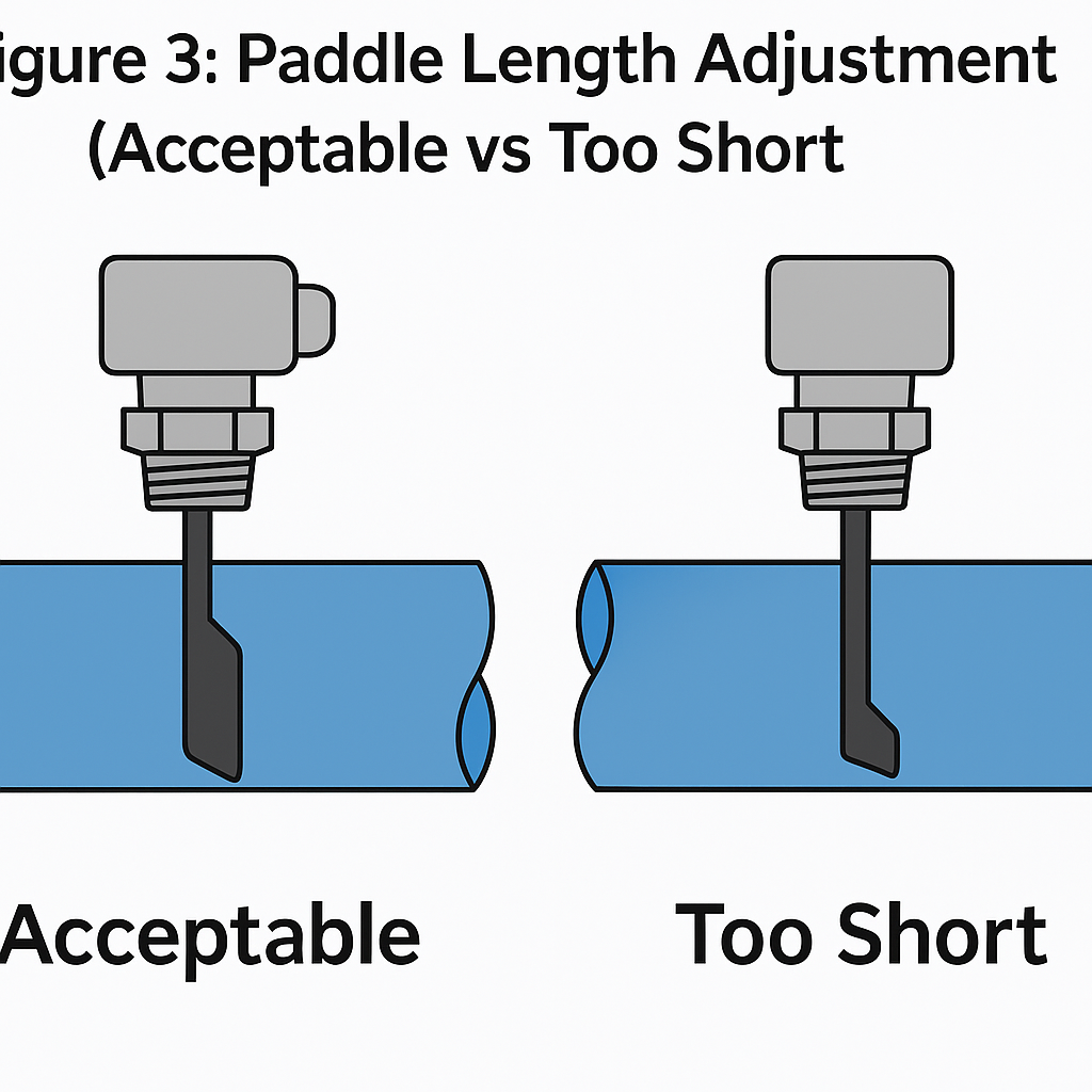
🔩 Paddle Length Consideration:
The paddle is detachable and can be trimmed based on installation requirements.
Do not cut too short, or it may reduce sensitivity or prevent switch activation.
Figure 3: Paddle Length Adjustment Guide
5. Medium Requirements
The medium should not contain fibrous or entangled debris, which may interfere with paddle movement or damage the switch.
6. Commissioning Tips
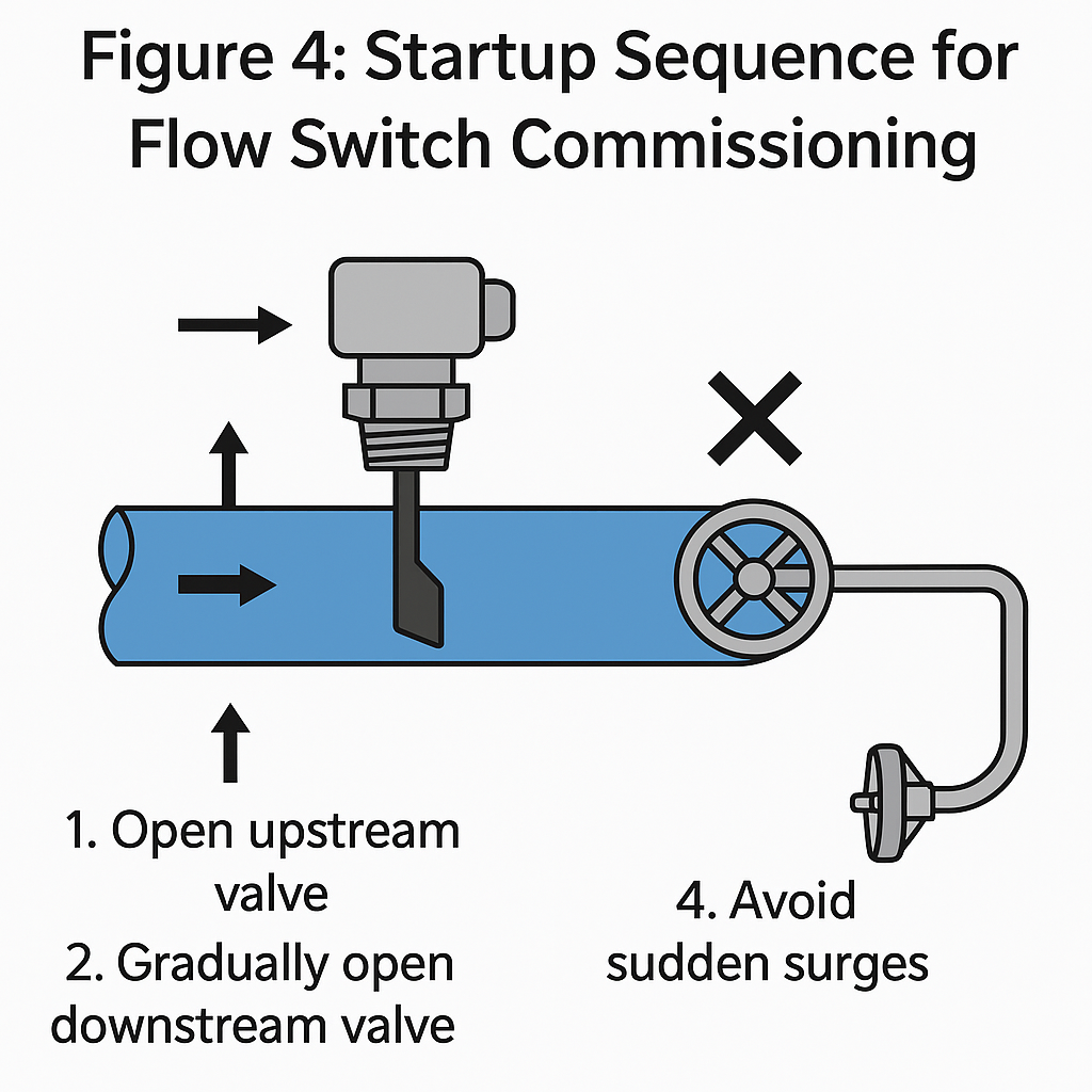
Before Starting Flow:
Close the downstream valve of the flow switch.
Open the upstream valve to fill the switch pipeline with fluid.
Start-Up:
Gradually open the downstream valve to slowly increase the flow rate.
Avoid sudden surges, which may damage the paddle or the internal mechanism.
Figure 4: Startup Sequence for Flow Switch Commissioning