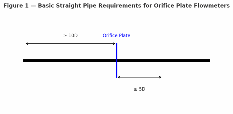
The accuracy of an orifice plate flowmeter largely depends on sufficient straight pipe runs upstream and downstream of the orifice plate. General recommendations are:
These values represent minimum requirements under normal conditions.
2. Influencing Factors and Special Conditions
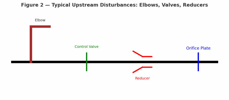
2.1 Pipe Configuration
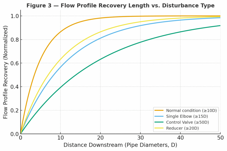
Single 90° Elbow (upstream): ≥ 15D
Two 90° Elbows in Different Planes (upstream): ≥ 30D or longer
Control Valve (fully open): ≥ 20D upstream
Control Valve (partially open): ≥ 50D upstream (depending on disturbance severity)
Reducer or Expander: ≥ 15D–20D upstream
2.2 Fluid Properties
High-Viscosity Fluids: Flow recovery is slower. Extend upstream length to 15D–20D or more.
Multiphase or Impurity-Laden Fluids: Presence of solids, vaporization, or condensation after throttling requires longer straight runs.
Recommended: ≥ 15D upstream, ≥ 5D–10D downstream
3. Standards and References
GB 50093-2013: Code for Construction and Quality Acceptance of Automation Instrumentation Engineering
GB/T 2624: Measurement of Fluid Flow by Means of Pressure Differential Devices Inserted in Circular Cross-Section Conduits Running Full
ISO 5167: International Standard for Differential Pressure Flow Measurement
4. Summary Table of Recommended Straight Pipe Lengths
Upstream Condition
Minimum Upstream Length
Minimum Downstream Length
Normal condition
10D
5D
Single 90° elbow
15D
5D
Two 90° elbows (different planes)
30D or more
5D
Control valve (fully open)
20D
5D
Control valve (partially open)
50D or more
5D
Reducer/Expander
15–20D
5D
High viscosity
15–20D or more
5–10D
Impurities/Phase change
15D or more
5–10D
5. Practical Notes
The above guidelines are general engineering practices. Actual installation should also consider space limitations, safety, and compliance with local standards.
In critical process control applications, using flow conditioners may reduce the required straight pipe length while maintaining accuracy.
Always refer to the latest edition of national and international standards for detailed configurations.