1. Pre-Installation Preparation
• Component Inspection
Before installation, inspect each valve in the manifold carefully. Ensure that all valves operate smoothly, without sticking or leakage. Also, check the pressure impulse lines, pipe fittings, and other connectors for any damage and confirm that the dimensions are compatible.
• Cleaning
Clean the installation site and connection interfaces to remove dust, oil, rust, or any foreign particles. This ensures a reliable seal during installation.
2. Installation Site Selection
• Ease of Operation and Maintenance
The manifold should be installed in an easily accessible location for operation and maintenance. Typically, it is installed adjacent to the differential pressure transmitter, with sufficient clearance for manual operation and servicing.
• Avoiding Interference
Avoid placing the manifold near vibration sources, heat sources, or strong electromagnetic fields, as these may affect measurement accuracy. If installed near high-temperature equipment, thermal insulation measures should be adopted.
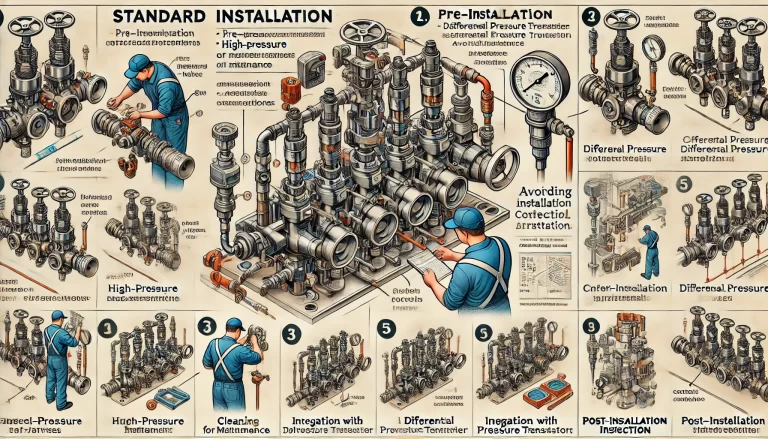
3. Confirming Installation Orientation
• Inlet and Outlet Direction
Most manifolds are marked to identify the high-pressure valve, low-pressure valve, and equalizing valve. Install the manifold strictly according to these markings to ensure proper fluid flow.
• Gravity and Fluid Considerations
If the process fluid may contain particulates or condensate, install the manifold in an orientation that facilitates drainage, preventing buildup that could affect measurement accuracy.
4. Connection and Tightening
• Sealing Components
When connecting the manifold to piping or equipment, ensure appropriate sealing elements (e.g., O-rings, gaskets) are properly installed. The material of the seals must be compatible with the process media to prevent leakage.
• Bolt Tightening
Use suitable bolts, nuts, and washers. Tighten bolts moderately to avoid deformation or damage, using a diagonal pattern to ensure uniform stress distribution.
5. Integration with Differential Pressure Transmitter
• Face-to-Face Alignment
When connecting the manifold to a differential pressure transmitter, ensure both interfaces are clean, flat, and properly aligned. Misalignment may cause sealing failure or measurement errors.
• Appropriate Spacing
The connection piping between the manifold and transmitter should be as short as possible to minimize pressure loss and measurement error, while still allowing sufficient room for installation and maintenance.
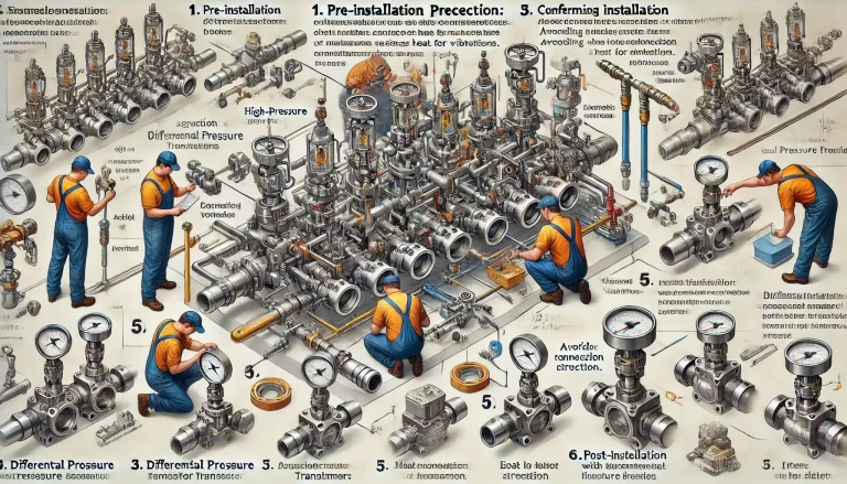
6. Post-Installation Inspection
• Visual Check
Ensure the manifold is securely mounted and that there is no visible damage or deformation.
• Leak Testing
Perform a leak test by closing all valves, applying pressurized gas or liquid to the inlet, and observing for leaks. If any are found, identify the source and re-install or replace the sealing components as necessary.
• Functional Testing
Manually operate each valve in the manifold to confirm that the opening and closing actions are smooth and that the manifold correctly controls the flow and shut-off of the process media.
7. Installation Notes and Common Issues
Ensure valve alignment for proper sealing.
Do not overtighten bolts to avoid damaging flanges or valve bodies.
Use torque specifications provided by the manufacturer if available.
In high-vibration areas, consider using anti-vibration mounts.