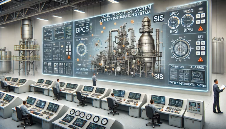
Introduction
In petrochemical production processes, the Safety Instrumented System (SIS) interlock logic is a crucial safety measure ensuring the safe operation of industrial processes. Various SIS interlock configurations, such as 1-out-of-1 (1oo1), 2-out-of-2 (2oo2), 2-out-of-1 (2oo1), and 3-out-of-2 (3oo2), are commonly used. Recently, a new configuration, 4-out-of-4 (4oo4), has been proposed. This article explores the selection criteria for SIS configurations, their impact on safety and availability, and practical methods for determining the optimal configuration.

1. SIS Interlock Logic Configurations and Their Influencing Factors
Selecting the appropriate SIS interlock configuration depends on several factors, including process characteristics, safety requirements, availability demands, and compliance with regulations. The most common configurations are:
1oo1 (One-out-of-One): The system triggers the interlock when the single input signal meets the trigger condition. However, a fault in the instrument may directly cause an unintended interlock activation, indicating high sensitivity but low fault tolerance.
2oo2 (Two-out-of-Two): Both input signals must meet the trigger condition to activate the interlock. A single instrument failure will not trigger the interlock, resulting in higher availability but lower safety integrity.
2oo1 (Two-out-of-One): The interlock activates if either of the two input signals meets the trigger condition. This configuration ensures that the system still operates if one instrument fails, providing higher safety integrity but lower availability due to the risk of spurious trips.
3oo2 (Three-out-of-Two): Any two out of three input signals must meet the trigger condition to activate the interlock. This configuration balances safety and availability, as it can tolerate a single instrument failure without causing spurious activation or refusal to trip.
4oo4 (Four-out-of-Four): All four input signals must meet the trigger condition for the interlock to activate. While this setup offers extremely high availability, its safety integrity is significantly reduced, making it rarely used in practice.

Influencing Factors in Configuration Selection:
Process Characteristics: Complex and high-risk processes require more reliable configurations to prevent hazardous incidents.
Safety Requirements: Higher safety demands necessitate configurations with stronger fault tolerance (e.g., 3oo2) to minimize the risk of failure.
Availability: A balance between safety and operational continuity must be achieved. Overemphasis on safety may compromise availability, and vice versa.
Compliance: Regulatory standards, such as Safety Integrity Level (SIL), Hardware Fault Tolerance (HFT), and System Capability (SC), must be met, as outlined in standards like GB/T21109 and GB/T20438.
2. Methods for Determining SIS Configuration
Selecting the optimal SIS configuration involves a multi-step evaluation process:
Safety Assessment: Conduct comprehensive risk assessments to analyze process hazards, potential failure modes, and their impacts. The results guide the selection of the most appropriate configuration.
Functional Requirements Analysis: Clearly define SIS logic requirements, including input/output signal types, trigger conditions, and logical relationships. This forms the basis for configuration selection.
Standards and Guidelines: Refer to industry standards and guidelines such as GB/T21109 (IEC 61511), GB/T20438 (IEC 61508), and ISA 84 for configuration rules and recommendations. For example, HFT requirements must be satisfied to meet specific SIL levels.
Experience and Expertise: Utilize insights from previous projects and expert recommendations, especially in similar process scenarios, to inform configuration decisions.
Feasibility Analysis: Evaluate the technical feasibility, cost-effectiveness, reliability, and maintenance demands of candidate configurations to identify the most suitable option.

3. Case Studies in the Petrochemical Industry
Case 1: Transition from 1oo1 to 2oo1 for SIL2 Compliance
In a process requiring SIL2 compliance, the initial 1oo1 configuration posed a high risk of spurious trips. According to GB/T20438.2-2017 (Route 1H), the system required HFT = 1. By upgrading to a 2oo1 configuration with SC3-rated instruments, the system achieved the required SIL2 level. SIL verification confirmed the configuration’s effectiveness, and to enhance availability further, a 3oo2 setup was proposed.Case 2: Adoption of 3oo2 Configuration for High Safety and Availability
Another process required SIL2 compliance with high operational availability. Following safety assessments and HFT requirements, a 3oo2 configuration was selected. SIL calculations verified that this setup met the failure rate criteria, balancing safety integrity and process uptime.

4. Conclusion
Selecting an SIS interlock configuration demands a careful balance of safety, availability, and compliance with industry standards. Configurations like 3oo2 offer an optimal balance, whereas configurations like 4oo4, despite high availability, are impractical due to poor safety integrity. A systematic approach involving safety assessments, functional analysis, regulatory compliance, and feasibility studies ensures the most effective and reliable configuration is chosen. Collaborating with experienced engineers further enhances the decision-making process, ensuring both safety and operational efficiency in petrochemical industries.
