In modern industrial automation, sensors and controllers are like the “nervous system” and “brain” of the entire control process. Sensors act as the system’s eyes, ears, and skin—detecting external conditions—while controllers make decisions and issue commands based on the sensor feedback.
They work in seamless coordination to ensure systems operate intelligently, accurately, and efficiently.
1. What Is a Sensor? — The System’s Sensory Organs
A sensor collects physical information—such as temperature, pressure, level, or density—from the environment and converts it into an electrical signal for the control system.
🔧 How Does a Sensor Work?
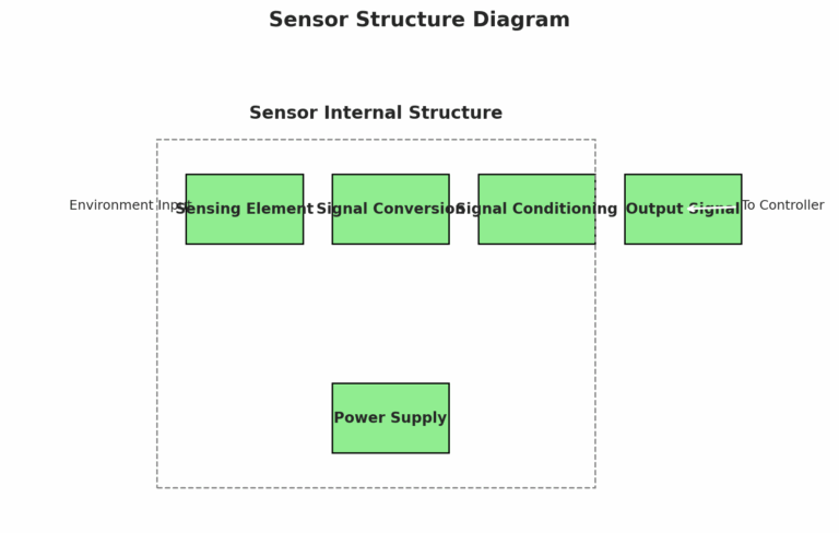
A typical sensor consists of:
Sensing element – Detects changes in the environment.
Examples: A thermocouple for temperature, a microwave antenna for radar level sensing, or a piezo-driven tuning fork for point level detection.Conversion element – Converts the physical quantity into an electrical signal.
Signal conditioning circuit – Amplifies, filters, or modulates the signal to make it readable by the controller.
Power supply – Ensures stable operation of the sensor.
📌 Common Sensor Types
| Measurement Type | Sensor Examples |
|---|---|
| Temperature | Thermocouples, RTDs |
| Pressure | Piezoelectric, Strain Gauge Sensors |
| Flow | Turbine, Ultrasonic Flow Meters |
| Level | Float-type, Radar, Tuning Fork Switches |
Application Example: Boilers use temperature sensors; storage tanks use level sensors.
2. What Is a Controller? — The Brain of the System
Once the sensor collects data, the controller interprets that data and decides what action to take. Think of it as the brain of the system.
🔍 How Does a Controller Work?
Input – Receives sensor signals (e.g., “current level: 75 mL”).
Comparison – Compares actual value against a setpoint (e.g., 90 mL).
Computation – Uses control algorithms (often PID) to determine required action.
Output – Sends a command to an actuator (e.g., “open valve to fill tank”).
Feedback Loop – Sensor updates value; controller adjusts accordingly.
🧠 Internal Structure
Input Module – Accepts sensor data.
Processing Unit – Performs logic, computation, and decision-making.
Output Module – Sends control signals (analog or digital) to actuators or devices.
3. Key Differences Between Sensors and Controllers
| Aspect | Sensor | Controller |
|---|---|---|
| Role | Data acquisition | Decision-making and control |
| Signal Type | Weak analog signals (e.g., mV) | Strong signals (e.g., 4–20 mA, relay output) |
| Functionality | Passive, monitors only | Active, computes and issues commands |
| Position in System | Front-end of automation loop | Central processing core |
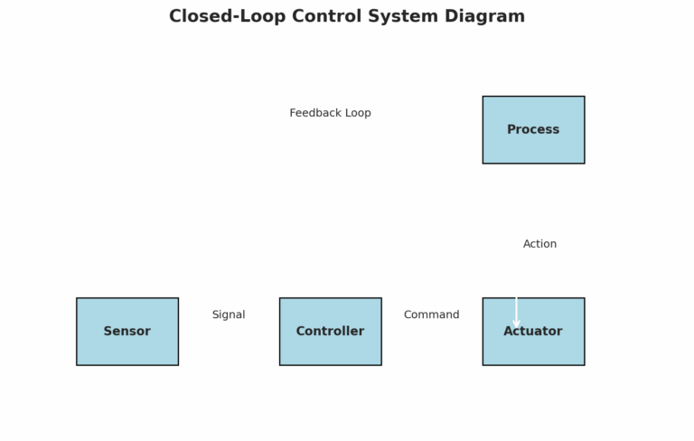
4. How Do They Work Together?
An automated system operates in a closed-loop where the sensor and controller cooperate continuously.
Example – Level Control System:
The sensor constantly monitors the liquid level.
The controller receives the data and checks if the level is within the desired range.
If the level is too high, the controller commands the actuator to stop feeding or discharge.
Once the level returns to normal, the sensor updates the status, and the controller resumes operation if needed.
This loop repeats continuously—maintaining balance and stability without manual intervention.

5. Conclusion
In essence, a reliable automation system requires tight coordination between sensors (data collectors) and controllers (decision-makers).
Sensors gather critical real-time data.
Controllers process this data and execute appropriate actions.
With the rise of smart factories, both components are becoming more advanced—supporting high-speed processing, digital communication (like HART, Modbus, or Profibus), and integrated diagnostics.
They are the driving forces behind the future of industrial intelligence.