In industrial electrical control systems, the concepts of self-locking, interlocking, and mutual locking are fundamental. Although similar in terminology, each has distinct logic, application, and purpose. This document provides a structured comparison of these three control methods, with definitions, working principles, typical applications, and schematic diagrams.
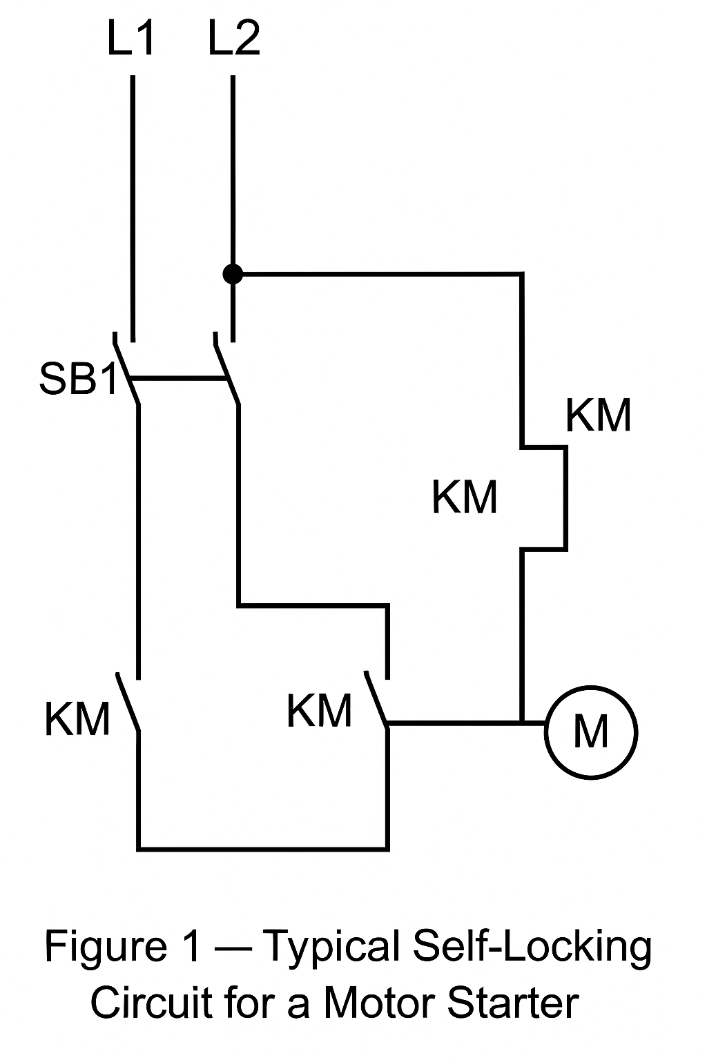
2. Self-Locking (Hold-On Circuit)
2.1 Definition
Self-locking refers to the ability of a control element (such as a relay or contactor) to maintain its energized state even after the initiating signal disappears.
2.2 Working Principle
A normally open (NO) auxiliary contact of the relay or contactor is wired in parallel with the start button. Once the button is pressed, the contactor energizes and its NO auxiliary contact closes, forming a holding circuit. This maintains the energized state even after the button is released.
2.3 Application
Motor start/stop circuits
Processes requiring continuous operation after a single trigger
2.4 Advantages
Simplifies operator action (no need to hold the button continuously)
Ensures stable equipment operation
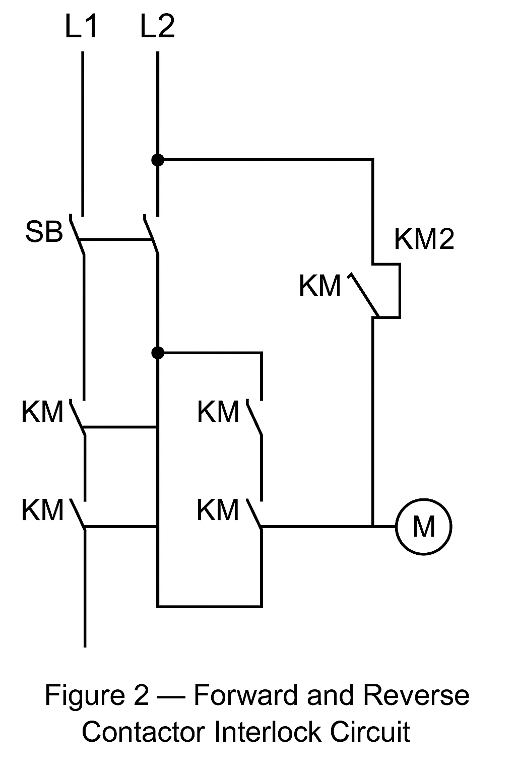
3. Interlocking
3.1 Definition
Interlocking is a logic relationship that prevents two or more devices from operating simultaneously, avoiding conflicts or unsafe conditions.
3.2 Working Principle
When one device is energized, the interlock contacts (normally closed) are opened in the control loop of the other device, preventing it from being energized at the same time.
3.3 Application
Forward/reverse motor control
Sequential control of multiple motors (start/stop order)
Safety protection where mutual exclusion is required
3.4 Advantages
Prevents short circuits and equipment conflicts
Improves safety and system reliability
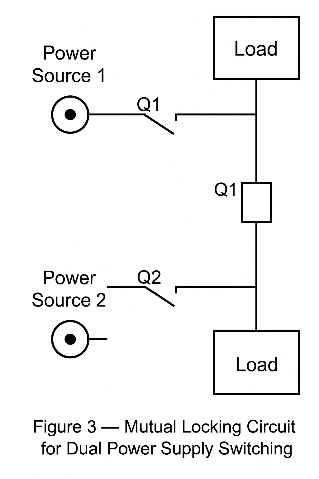
4. Mutual Locking
4.1 Definition
Mutual locking refers to a condition where two or more devices restrict each other’s operation in such a way that one can only run if the other is in a defined state. It emphasizes dependency and coordination, not just exclusion.
4.2 Working Principle
Auxiliary contacts of each contactor are wired in series with the control circuit of the other. When one contactor energizes, it blocks the other’s control path, ensuring coordinated operation.
4.3 Application
Dual power supply transfer switches (only one source can be active at a time)
Coordinated machine operation where dependency is required
4.4 Advantages
Ensures synchronization between devices
Prevents unsafe independent operation
5. Comparative Summary
Table 1 — Comparison of Self-Locking, Interlocking, and Mutual Locking
Mechanism
Definition
Main Function
Typical Application
Self-Locking
Holds device state after trigger
Simplifies control, maintains operation
Motor start/stop control
Interlocking
Prevents simultaneous operation
Avoids conflicts, enhances safety
Forward/reverse motor circuits
Mutual Locking
Devices restrict each other’s operation
Ensures dependency and coordination
Dual power supply switching
6. Conclusion
Self-locking, interlocking, and mutual locking are core principles in electrical circuit design.
Self-locking simplifies operator control.
Interlocking ensures safety by preventing conflicts.
Mutual locking provides coordination in systems requiring dependency.
Understanding and applying these principles correctly is essential for safe and efficient electrical control system design.