In Safety Instrumented Systems (SIS), Safety Integrity Level (SIL) quantifies the required risk reduction. However, even within the same SIL rating, different configurations of pressure transmitters can significantly impact practical safety performance, reliability, and maintenance complexity.
This article explores:
Why different configurations matter under the same SIL
Common pressure transmitter setups
Their relative safety differences
Engineering case examples
2. Understanding SIL and Transmitter Configuration
SIL measures probability of failure on demand (PFD) or probability of dangerous failure per hour (PFH).
Transmitter configuration refers to the physical setup and logic of one or multiple pressure transmitters used to achieve the safety function.
Even if multiple setups meet the mathematical PFD requirements for SIL2 or SIL3, their real-world performance can differ in:
Failure detection speed
Maintenance needs
False trip rates
Resilience to common-cause failures
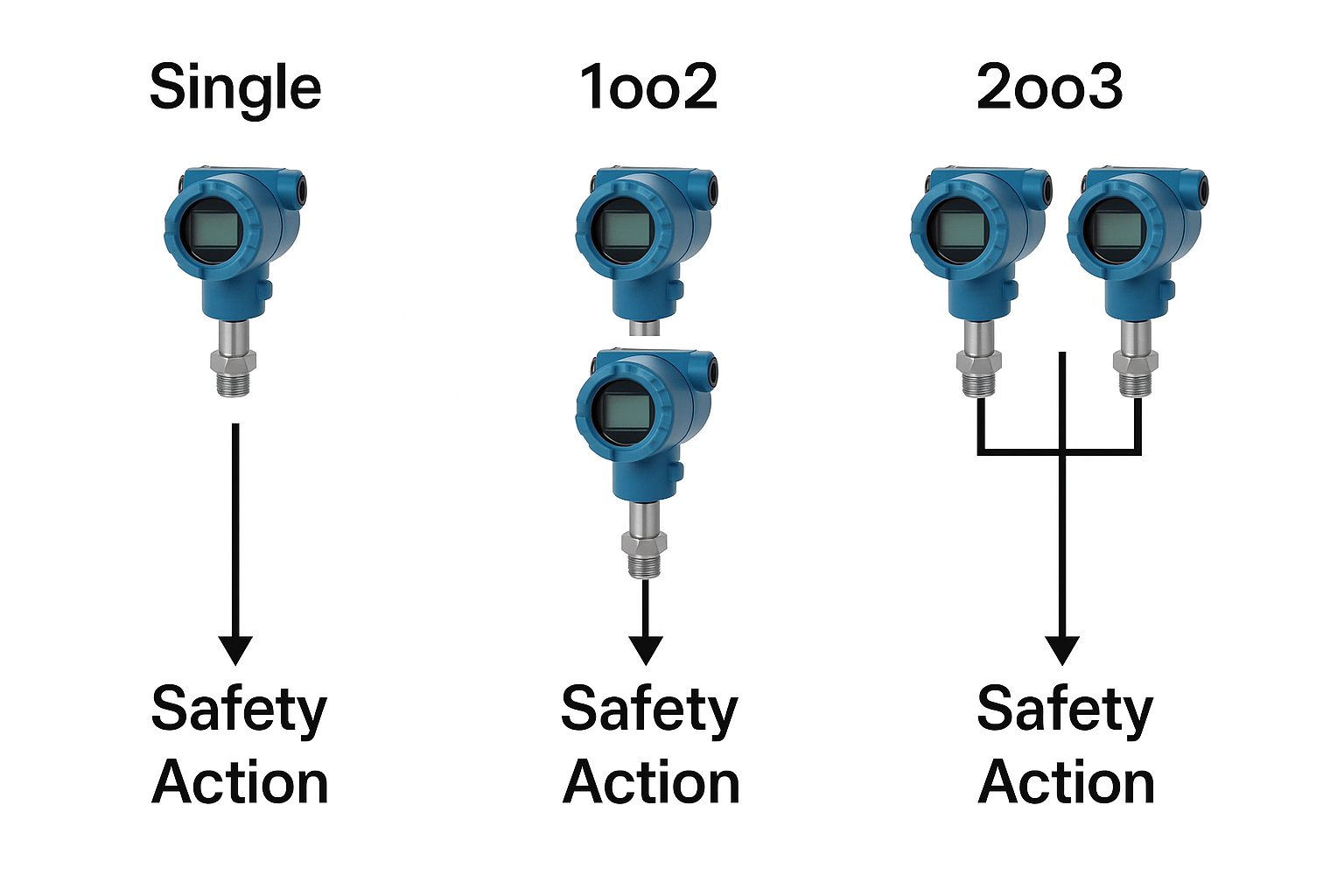
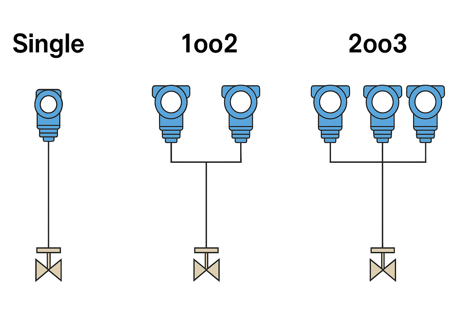
3. Typical Pressure Transmitter Configurations
Configuration
Description
Key Characteristics
Single Transmitter
One transmitter triggering the safety action
Simple, low cost, but single-point failure risk
1oo2 (One-out-of-Two)
Two transmitters, any one triggers action
Higher availability, tolerant to one failure
2oo3 (Two-out-of-Three Voting)
Three transmitters, at least two must agree
High safety, detects failure early, reduces false trips
Redundant Single Loop
Main + backup transmitter, manual or automatic switchover
Improves reliability but still needs manual testing
Smart Diagnostics (Heartbeat Technology, etc.)
Advanced transmitter with self-diagnosis features
Enhances fault detection without extra hardware
4. Safety Differences Analysis
4.1 Single Transmitter
Pros: Lowest cost, simplest installation.
Cons: A dangerous undetected failure will compromise the safety function completely.
Typical: Only acceptable for low-demand SIL1 applications or where redundancy is not economically feasible.
4.2 1oo2 Redundancy
Pros: System remains functional if one transmitter fails.
Cons: Potential for spurious trips if one device malfunctions and triggers the safety function unnecessarily.
4.3 2oo3 Voting
Pros:
Highest fault tolerance.
Early fault detection possible (automatic deviation monitoring).
Greatly reduces nuisance trips.
Cons:
Higher initial cost and maintenance complexity.
Requires careful installation to avoid common-cause failures (e.g., same tapping point, same cable route).
4.4 Redundant Single Loop
Pros: Moderate improvement over single transmitter.
Cons: Backup unit needs regular manual proof testing; no automatic fault detection between tests.
4.5 Smart Diagnostics
Pros:
Detects sensor drift, blockage, or calibration loss.
Lower cost than full 2oo3 hardware redundancy.
Cons:
Only detects certain types of failures, cannot cover total hardware failures.
5. Engineering Case Studies
Case 1: SIL2 Pressure Protection for Steam Drum
Original Design: Single transmitter
Issue: Failure not detected between proof tests → unexpected high drum pressure
Improvement: Upgraded to 1oo2 architecture
Result: Availability increased, SIL2 requirement still satisfied, annual maintenance updated to check both transmitters.
Case 2: SIL3 High-Pressure Shutdown in Offshore Platform
Design: 2oo3 voting of three transmitters from different manufacturers, separate tap points.
Result: Zero shutdown incidents for three years, even in extreme offshore conditions.
Case 3: SIL2 Ammonia Tank Level Protection (Using Pressure Measurement)
Design: Redundant single loop, with automatic switchover.
Issue: Backup transmitter not tested for 18 months → detected failure during audit.
Lesson: Even “redundant” systems need periodic proof testing to ensure actual availability.
6. Practical Recommendations
For SIL1: Single transmitter with smart diagnostics may be sufficient.
For SIL2: 1oo2 is recommended; single transmitter discouraged unless risk assessment proves acceptable.
For SIL3: Always prefer 2oo3 voting or advanced diagnostics + partial redundancy.
Always mitigate common-cause failures:
Physically separate cabling
Use different measurement taps if possible
Diversify vendors or sensor types for higher robustness.
Conclusion
Even under the same SIL target, different pressure transmitter configurations lead to very different safety performances in real projects. Proper selection of configuration not only achieves the formal SIL target but also ensures reliable, sustainable, and cost-effective system operation.