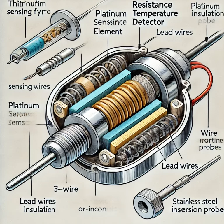
Resistance Temperature Detectors (RTDs), such as the widely used Pt100, are temperature sensors that exploit the predictable change in electrical resistance of a metal (typically platinum) as temperature varies. By measuring the resistance of the RTD element, one can accurately determine temperature.
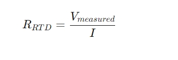
A temperature transmitter supplies a known excitation current to the RTD and measures the resulting voltage drop. This voltage, combined with the known current, allows calculation of the resistance using Ohm’s law:
This resistance is then converted to a temperature value based on the RTD’s standard resistance-temperature characteristics.
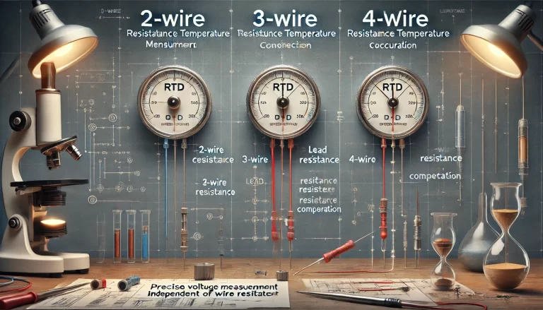
However, the accuracy of this measurement is significantly affected by the resistance of the connecting wires between the RTD and the transmitter. To mitigate this issue, three main wiring configurations are used: two-wire, three-wire, and four-wire.
2. Two-Wire RTD Configuration
Working Principle
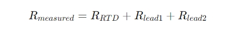
In the two-wire method, the RTD is connected to the transmitter using two lead wires. The excitation current flows through both the RTD and the lead wires. The transmitter measures the total voltage drop across the entire loop:
Drawback
This configuration is simple and cost-effective but cannot compensate for lead wire resistance. As a result, the measured resistance includes both the RTD and the wire resistances, introducing error.
Example
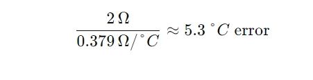
If each lead wire has 1 Ω resistance and the RTD sensitivity is 0.379 Ω/°C (as with Pt100 at ~100 °C), a 2 Ω lead resistance results in:
3. Three-Wire RTD Configuration
Working Principle
To reduce the effect of lead resistance, a third wire is added. This third wire is connected to a high-impedance voltage measurement circuit. If the three wires are identical in length, material, and ambient conditions (so RL1=RL2=RL3), then the voltage drop caused by lead resistance can be mathematically cancelled.
The transmitter applies current through two wires and measures the voltage via the third, compensating for the resistance error.
Advantage
This is the most commonly used configuration in industrial applications, providing good accuracy with minimal additional wiring cost.
4. Four-Wire RTD Configuration
Working Principle
The four-wire configuration is the most accurate. Two wires are used to carry the excitation current, and the other two are used exclusively for voltage measurement. These voltage-sensing wires are connected to a high-impedance input, so they carry negligible current, and thus do not introduce any significant voltage drop.
Advantage
Since the voltage is measured directly across the RTD with no current in the sensing wires, this method eliminates the influence of lead resistance entirely.
5. Comparison Table
Configuration
Lead Wires
Compensation for Lead Resistance
Accuracy
Cost
Two-Wire
2
❌ None
Low
Low
Three-Wire
3
✅ Partial
Medium–High
Medium
Four-Wire
4
✅✅ Full
Very High
Higher
6. Conclusion
The choice of RTD wiring configuration depends on the required measurement accuracy and cost constraints:
Two-wire: Suitable for short distances and non-critical applications.
Three-wire: The most practical solution for most industrial installations.
Four-wire: Recommended for laboratory or high-precision applications.
Understanding and selecting the appropriate wiring method can significantly improve temperature measurement reliability in your instrumentation system.