Resistance Temperature Detectors (RTDs) are widely used in industrial applications for accurate and stable temperature monitoring, especially within low to medium temperature ranges. This article provides a comprehensive overview of RTD working principles, materials, types, wiring methods, troubleshooting techniques, and installation guidelines.
1. Principle of RTD Temperature Measurement
RTDs operate based on the principle that the electrical resistance of a metal changes with temperature. As the temperature rises, the resistance of the RTD element increases in a predictable manner. By detecting the change in resistance and converting it through a Wheatstone bridge into a voltage signal, the temperature can be measured accurately.

2. RTD Materials and Their Characteristics
While many metals exhibit resistance changes with temperature, only a few meet the criteria for use in RTDs:
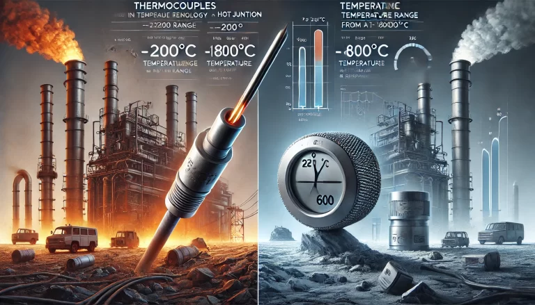
Platinum (Pt): Offers high accuracy, excellent stability, and repeatability. Suitable for neutral and oxidizing environments. Common types include Pt100, Pt1000.
Copper (Cu): Provides good linearity within its range, but oxidizes easily above 150°C. Common models include Cu50 and Cu100.
Other Materials: Nickel, manganese, and rhodium are also used in some applications.
Key requirements for RTD materials:
High and stable temperature coefficient of resistance (TCR)
High resistivity for smaller sensor sizes
Chemical and physical stability
Reproducibility and near-linear resistance-temperature characteristics
3. Classification of RTDs
3.1 By Sensing Element Material
Platinum RTDs: Pt10, Pt100, Pt1000
Copper RTDs: Cu50, Cu100
Others: Nickel-based or alloy RTDs for special applications
3.2 By Structural Design
Standard Type: Includes sensing element, mounting components, and terminal box. Pt100 is the most widely used.
Armored RTD: A compact, insulated assembly encased in stainless steel, offering:
Fast thermal response
Vibration and impact resistance
Flexible and easy installation
Extended service life
Explosion-Proof RTD: Equipped with a flameproof junction box to prevent ignition of explosive gases.
Surface RTD (End-Face): The sensor is pressed against the surface, enabling accurate temperature measurement of components like bearings.
4. RTD Wiring Methods
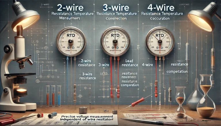
RTD wiring significantly impacts measurement accuracy. There are three common wiring configurations:
4.1 Two-Wire System
Simplest method but subject to significant error due to lead wire resistance. Suitable for low-accuracy applications.
4.2 Three-Wire System (Most Common)
Balances the lead wire resistance by connecting one wire to the excitation source and the other two to the bridge arms. Widely used in industrial control systems.
4.3 Four-Wire System (High Precision)
Completely eliminates the effect of lead wire resistance. Ideal for laboratory or high-accuracy environments.
5. Why the Three-Wire System is Preferred
In a three-wire system, two wires carry the bridge current, and one acts as a reference. This setup cancels out the resistance of the connecting leads, significantly reducing measurement error, especially over long distances.
6. Common RTD Troubleshooting Scenarios
| Issue | Cause | Solution |
|---|---|---|
| Display value too low or unstable | RTD not inserted deep enough, or protective sheath contains moisture | Adjust insertion depth and dry/clean sheath |
| Signal interference | No shielding, improper cable routing, grounding issues | Use shielded cables, follow cable separation rules, ensure single-point grounding |
| No reading | Broken element or disconnection | Check continuity, replace damaged parts |
Additional mitigation: use anti-interference capacitors in three-phase RTD setups if electromagnetic noise persists.
7. RTD Installation Guidelines
Positioning: Choose locations where medium temperature is accurately and responsively reflected. Avoid dead zones.
Insertion Depth: Ensure full immersion of the sensing element. For pipe installations, consider wall thickness and connection head length:
L = L1 + δ + U
where
L1is connection head length,δis wall thickness, andUis immersion depth.Bending Radius and Support: For horizontal insertions, cantilever length should not exceed 600 mm.
Tank and Vessel Installations: Avoid obstructing moving parts such as floating roofs; maintain adequate clearance from internal structures.
Thermowell Use Cases: Required in high-pressure, high-speed flow, or flammable media environments.