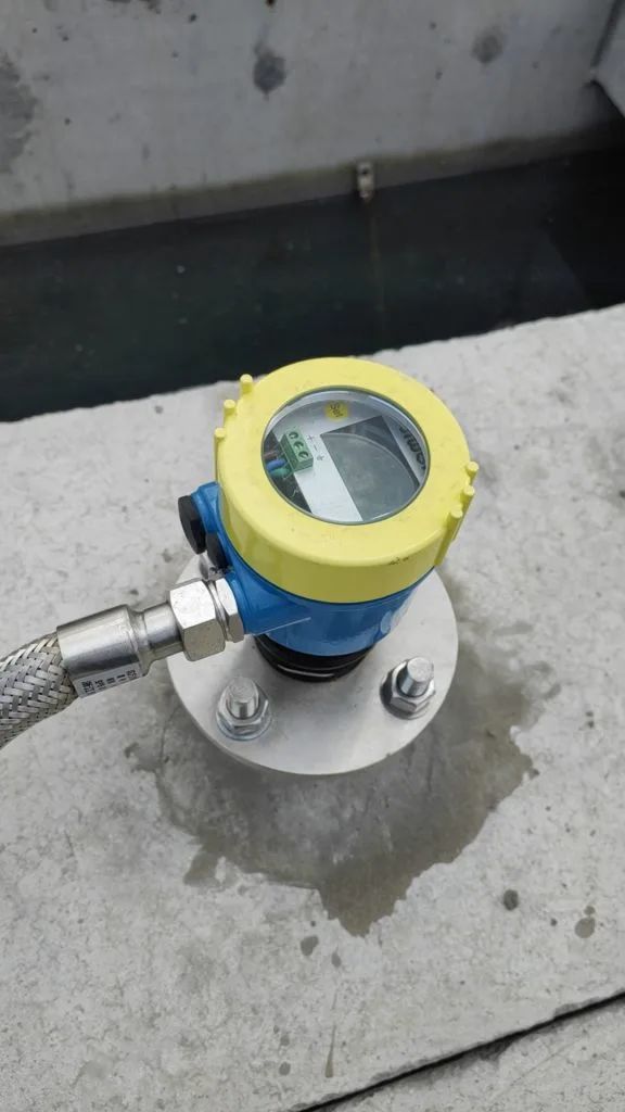
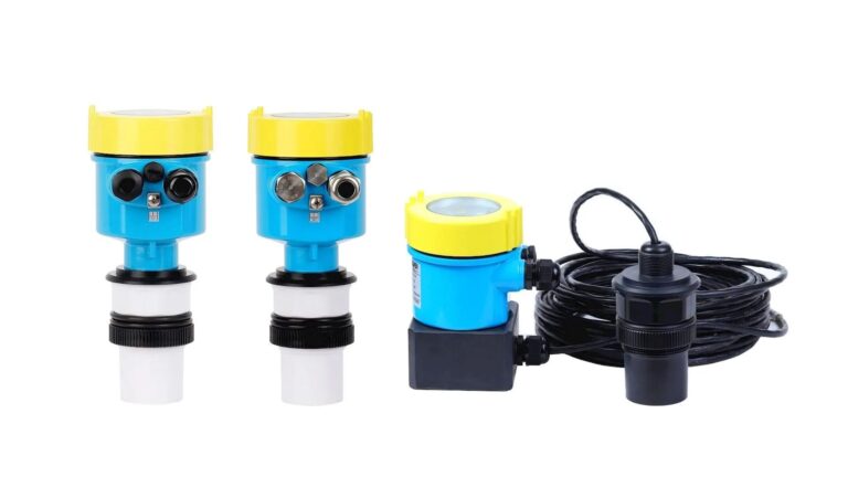
Ultrasonic level transmitters are widely used in industrial applications for continuous level monitoring. Proper maintenance ensures their measurement accuracy and prolongs service life. This guide outlines detailed and practical maintenance steps for four-wire ultrasonic level meters.
1. Sensor Surface Cleaning
Regular Cleaning
Use a clean, soft cloth or cotton swab moistened with alcohol to gently wipe the sensor surface.
Remove any dust, oil, or dirt that may interfere with the transmission and reception of ultrasonic waves.
Do not use chemical solvents or abrasive tools to avoid damaging the protective coating.
In Harsh Environments
For high-temperature or corrosive environments, clean the probe at least once a month.
Inspect for surface corrosion or degradation, especially for sensors made of PVDF or PTFE. Dullness may indicate material fatigue.
2. Cable and Connection Inspection
Cable Protection
Check that the outer insulation of signal and power cables is intact—especially in moist or rodent-prone environments.
Shielded cables should be routed in separate metal conduits, spaced at least 20 cm from power cables, and grounded properly with resistance ≤ 4 Ω.
Connector Tightness
Periodically inspect signal and power connectors for looseness or oxidation.
Retighten or replace terminals as necessary to ensure reliable transmission.
3. Calibration and Performance Verification
Scheduled Calibration
Perform zero-point calibration (empty tank) and full-scale calibration (liquid level at ≥90%) every six months.
If measurement error exceeds 1%, consider adjusting the probe angle or recalibrating device parameters.
Temperature Compensation
Activate automatic temperature compensation, or manually adjust the speed of sound based on the medium’s concentration (e.g., acid/alkaline solutions).
Signal Strength Monitoring
Use the device’s self-diagnostic function or an oscilloscope to verify echo signal strength. Recommended strength: ≥80%.
Weak signals may indicate improper installation height or sensor surface contamination.
4. Installation and Environmental Checks
Mechanical Stability
Ensure the probe’s vertical alignment deviation is within ±3° to avoid unstable readings.
Confirm that mounting bolts are secure to prevent vibration, shifting, or falling.
Environmental Adaptability
High-temperature scenarios: For split-type installations, keep the distance between sensor and transmitter ≤ 15 meters. Install heat sinks if the temperature exceeds 150°C.
Outdoor installations: Verify that the IP68-rated enclosure is sealed. Apply silicone at the cable entry to prevent rainwater intrusion.
5. Power Supply and Electronics Maintenance
Power Stability Monitoring
Regularly measure supply voltage: typically DC 24V or AC 220V.
Voltage fluctuations must remain within ±10% to protect internal circuits.
Use voltage regulators to minimize sudden power surges.
Electronic Component Check
Inspect circuit boards for burn marks or discoloration.
Check if heat sinks are operating within normal temperature limits (≤ 60°C).
Replace aging components promptly to maintain system integrity.
6. Special Condition Maintenance Strategies
Scenario
Recommended Measures
Strong Electromagnetic Interference
Install a dedicated ground rod or shield the device with a metal enclosure.
Foam or Steam Disturbance
Use a guiding pipe (≥100 mm diameter) or switch to a high-frequency (80 kHz) probe.
Low-Temperature Anti-Freeze
Equip the probe with a protective enclosure or heating belt to prevent ice buildup.
Conclusion
Implementing these maintenance steps can significantly enhance the performance and longevity of four-wire ultrasonic level transmitters. Consistent inspection and calibration help ensure a typical static accuracy of ±0.3% or better.