The installation of rotor flowmeters directly impacts measurement accuracy and service life. The following technical requirements must be strictly adhered to, with key details illustrated by the diagrams provided.
1. Core Installation Principles
1.1. Flow Direction and Vertical Alignment
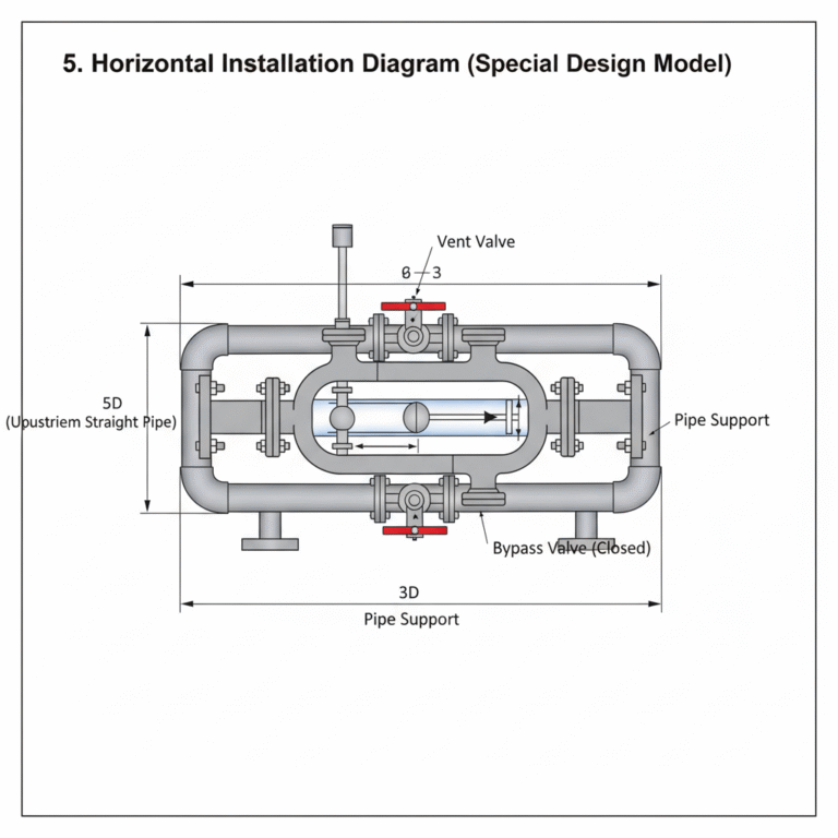
The rotor flowmeter must be installed vertically, with fluid flowing upwards through the tapered tube. The vertical alignment deviation should be no more than 2°. If horizontal installation is required (for specially designed models), the measurement tube must be kept level and fully filled with fluid, with a horizontal angle deviation of no more than 2°. Use a plumb line or level to calibrate the alignment to prevent the float from becoming stuck or distorting measurements.
1.2. Straight Pipe Segment Requirements
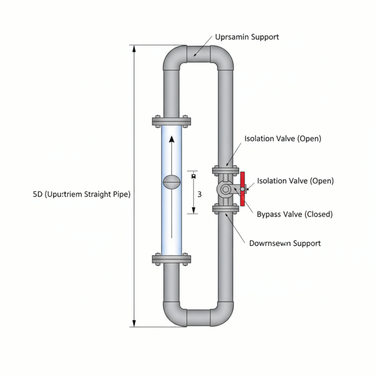
Upstream: At least 5 times the pipe diameter (5D) of straight pipe segment.
Downstream: Recommended to be 3 times the pipe diameter (3D) or at least 250mm. If there are bends, valves, or other flow disturbance components upstream, increase the straight segment length to 20-25 times the pipe diameter. For example, for a DN50 flowmeter, the upstream straight segment should be at least 250mm, and downstream should be at least 150mm.
2. Key Installation Steps and Precautions
2.1. Pre-installation Preparation
Pipeline Cleaning: Before installation, the pipeline must be purged to remove impurities like welding slag and iron filings, which could damage the float or block the measuring gap. If the medium contains ferromagnetic substances, install a magnetic filter at the inlet. For fluids with solid particles, install a regular filter.
Parameter Verification: Verify that the flowmeter’s maximum allowable temperature and pressure exceed the actual process conditions. For instance, if using a glass rotor flowmeter and the temperature exceeds 70°C, ensure a protective cover is installed.
2.2. Installation Process Control
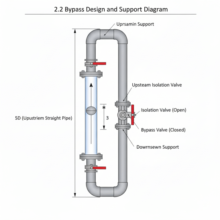
Support and Stress Relief: The pipeline should be fixed with supports to prevent the weight from directly affecting the flowmeter. For instruments with PTFE lining, ensure that flange nuts are tightened symmetrically to avoid deformation of the lining. For metal tube flowmeters, support the upstream and downstream pipes near the flanges to minimize vibration effects.
Bypass Design: Install a bypass pipe and valve (such as a ball valve or butterfly valve). During normal operation, the main pipe should be open and the bypass closed. For maintenance, switch to the bypass without interrupting production. The bypass pipe diameter is typically the same as the flowmeter’s, and valve placement should be easy to operate.
2.3. Connections and Sealing
Flange Matching: The flanges of the pipeline must be aligned and parallel with the flowmeter’s flanges, ensuring even bolt pressure to avoid deformation of the measurement tube. For example, ensure that the bolt holes of the DN80 flowmeter flange align perfectly with the pipeline flange, and use gaskets compatible with the medium.
Electrical Connections (if applicable): For electrical remote transmission flowmeters, check that the signal cables’ shielding layer is grounded to avoid electromagnetic interference. Explosion-proof versions must have sealed junction boxes that meet the explosion-proof standards.
3. Special Operating Conditions
3.1. Temperature and Vibration Protection
High-temperature Media (>70°C): For glass rotor flowmeters, install a metal protective cover and secure the upstream and downstream pipelines to prevent cracking due to thermal expansion or contraction.
Vibration Protection: When near pumps, compressors, or other vibration sources, install flexible joints or dampers before and after the flowmeter, or use liquid dampers to replace air dampers.
3.2. Differences Between Gas and Liquid Measurement
Liquid Measurement: Ensure the pipeline is completely filled with liquid to prevent bubbles from affecting the measurement. Install a vent valve at the highest point and evacuate the air from the body before starting.
Gas Measurement: When installed horizontally, ensure that the pipeline is always full to prevent liquid accumulation. When installed vertically, the fluid must still flow upwards.
4. Commissioning and Maintenance Points
4.1. Slow Start: Open the valve slowly to avoid fluid impact damaging the float. It is recommended to first fully open the bypass valve, then gradually close it, switching to the main pipeline.
4.2. Calibration and Cleaning: Regularly check the float’s mobility. If necessary, disassemble and clean (be careful not to damage the guiding rod). For electrical remote transmission models, check the accuracy of the 4-20mA signal output.
4.3. Long-term Idle Use: Empty the medium to prevent corrosion or crystallization. When handling glass rotor flowmeters, secure the float to prevent it from colliding with the tapered tube.
5. Typical Installation Diagrams
Vertical Installation (Standard Model): Fluid flows from bottom to top, with straight pipe lengths of 5D (upstream) and 3D (downstream). The bypass pipeline is parallel to the main pipeline, with valve placement for easy switching.
Horizontal Installation (Special Design Model): The measurement tube is placed horizontally with the fluid flowing perpendicular to the rotor axis. The upstream and downstream straight pipe lengths should follow the same requirements as vertical installation, with a vent valve at the low point.
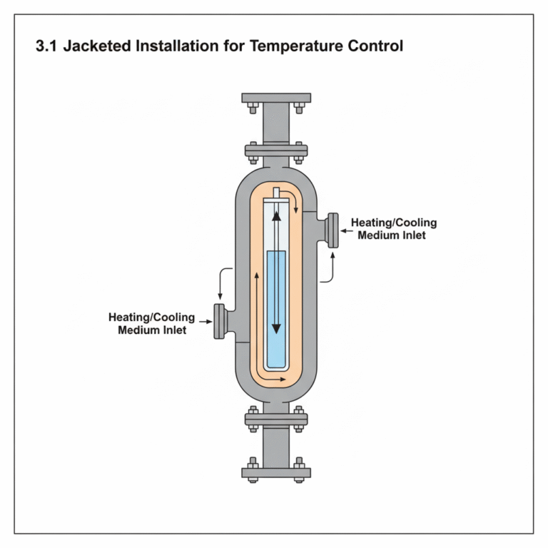
Jacketed Installation: For heating or cooling media to prevent condensation or vaporization, the inlet and outlet interfaces should be connected to the process pipeline. Tighten the flange bolts symmetrically to avoid deformation of the jacket.
6. Industry Standards and References
Domestic Standards: Follow the “Automation Instrumentation Engineering Construction and Acceptance Standards” GB50093-2013, with a focus on straight pipe length and grounding requirements.
International Standards: The German VDI/VDE 3513 standard provides methods for correcting flow meters for different fluid viscosities, suitable for high-precision measurements.
Manufacturer’s Manuals: Refer to the installation size tables for specific models, such as Shanghai Anrui Metal Rotor Flowmeter, to select the appropriate supports and pipe connections.
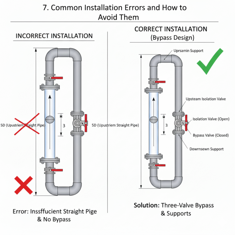
7. Common Installation Errors and How to Avoid Them
Error 1: Incorrect installation direction, causing the float to be unstable.
Solution: Ensure the flowmeter’s arrow direction matches the fluid flow direction. For vertical installation, fluid should enter from the bottom and exit from the top.
Error 2: Insufficient straight pipe segments, causing measurement fluctuations.
Solution: Reserve at least 5D (upstream) and 3D (downstream), or install straighteners to reduce turbulence.
Error 3: Failure to install a bypass, requiring shutdown during maintenance.
Solution: Install isolation and bypass valves on both sides of the flowmeter to form a “three-valve” structure.
Proper installation and regular maintenance will ensure that the rotor flowmeter operates stably, keeping measurement errors within ±1.5%FS (high-precision models can achieve ±1%FS). For actual operations, consult the technical manual for the specific model and have a professional technician perform the commissioning.