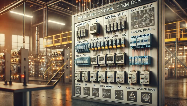
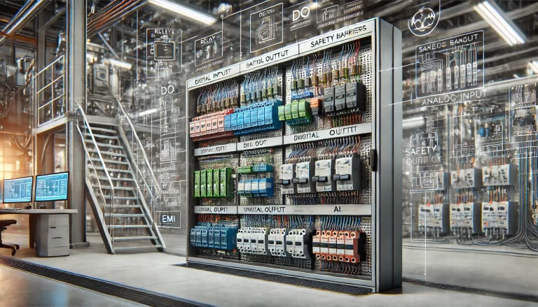
Distributed Control Systems (DCS) are widely used in industrial automation to monitor and control processes. This document explains the reasons for integrating relays with Digital Input (DI) and Digital Output (DO) points and safety barriers with Analog Input (AI) channels in DCS systems. The purpose is to enhance system reliability, ensure signal integrity, and meet operational requirements.

Relays in DI Points
Relays are often incorporated into DCS DI points for several critical reasons, including:
1. Electrical Isolation
Purpose: To prevent high-voltage or high-current signals from damaging the DCS system’s hardware, such as terminal boards and I/O modules.
Scenario: Electrical signals from field devices often carry substantial interference or higher voltages. For instance, in environments like substations, introducing a relay isolates strong electrical currents from reaching the DCS system, avoiding potential hardware failures.
2. Interference Suppression
Purpose: To mitigate external electromagnetic interference (EMI) that could distort or destabilize input signals.
Scenario: Relays help suppress noise and ensure that signals accurately represent the state of field devices. For example, in facilities with heavy machinery, the DI signals might encounter electrical noise. Using relays ensures stable and accurate signal transmission.
3. Signal Conversion and Adaptation
Purpose: To convert field signal types or voltage levels into formats compatible with DCS inputs.
Scenario: A field device might output a 220V AC signal, whereas the DCS DI module typically supports only 24V DC signals. Relays bridge this difference by enabling seamless voltage conversion and compatibility.
4. Logic Control and Interlocking
Purpose: To implement logical control functionalities using relay contacts.
Scenario: For instance, a fan system with sensors monitoring displacement, oil temperature, and oil levels can be connected to relays. If any sensor detects an anomaly, the relay interrupts the signal, triggering a safety shutdown of the fan.
5. Load Amplification
Purpose: To enhance the load-driving capability of the DI point.
Scenario: In cases where the field signal source cannot directly drive the DI input due to insufficient current or voltage, relays amplify the signal to meet the required levels.
Relays in DO Points
For DCS DO points, relays serve similar and additional purposes:
1. Electrical Isolation and Protection
Purpose: To isolate the DCS’s low-voltage signals from high-voltage or high-power field devices.
Scenario: The DCS DO module typically outputs 24V DC signals, whereas field devices might operate on 220V AC or higher. Relays ensure safe isolation, preventing high voltage from damaging the system.
2. Interference Suppression
Purpose: To shield the system from electromagnetic interference in complex industrial environments.
Scenario: Relays block interference signals, ensuring the stability and reliability of DO outputs.
3. Signal Conversion and Voltage Matching
Purpose: To adapt DCS output voltages to the requirements of field devices.
Scenario: A DCS system might control a pump requiring a 110V AC signal. Relays facilitate the conversion from the 24V DC output to 110V AC, ensuring compatibility.
4. Load Driving Capability
Purpose: To drive high-current or high-power devices that exceed the direct capacity of the DO module.
Scenario: When a motor requires a higher starting current, a relay can amplify the DO output to meet the motor’s demand.
5. Logic Control and Sequencing
Purpose: To implement logical operations and interlocks for safe operation.
Scenario: Relays can manage the sequence of motor startups or implement safety interlocks that prevent simultaneous operations of conflicting systems.
6. Ease of Maintenance
Purpose: To simplify troubleshooting and fault identification.
Scenario: When a field device malfunctions, relays provide a convenient point for checking signal flow, allowing faster maintenance and reducing downtime.
Safety Barriers in AI Channels
Safety barriers are critical for Analog Input (AI) channels in DCS systems, particularly in hazardous environments. Their inclusion serves the following purposes:
1. Explosion Protection
Purpose: To limit the energy transmitted to hazardous areas, preventing accidental ignitions.
Scenario: In industries like petrochemical or natural gas, safety barriers ensure that even in case of a fault, the energy transmitted to the hazardous area remains below the ignition threshold.
2. Electrical Isolation and Interference Suppression
Purpose: To isolate field signals from the DCS and block electromagnetic or ground loop interferences.
Scenario: Safety barriers isolate and stabilize signals from field devices in harsh environments, ensuring the DCS receives accurate and interference-free data.
3. Signal Conditioning and Adaptation
Purpose: To convert and process field signals for compatibility with DCS systems.
Scenario: For example, signals from thermocouples or RTDs are conditioned (filtered, amplified, or standardized) by safety barriers to ensure compatibility with the AI modules.
4. Equipment Protection
Purpose: To safeguard DCS hardware against over-voltage or over-current conditions.
Scenario: If a short circuit occurs in the field device, the safety barrier prevents damage to the DCS’s sensitive components, such as analog input cards.

Conclusion
The integration of relays in DI and DO points and safety barriers in AI channels is crucial for ensuring the reliability, safety, and efficiency of DCS systems. Relays provide electrical isolation, signal conversion, load amplification, and logic control, while safety barriers enhance explosion protection, signal conditioning, and hardware protection. Together, they form the backbone of robust industrial automation, safeguarding equipment and personnel while optimizing system performance.