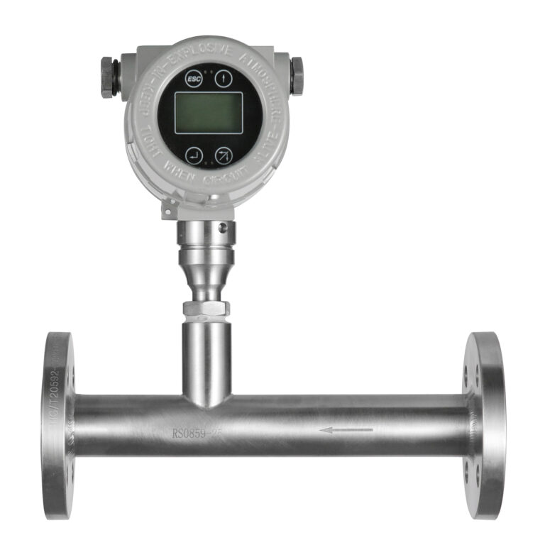
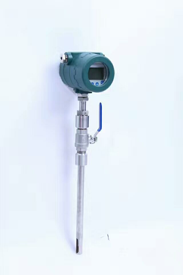
Thermal mass flow meters, commonly used for measuring the mass flow rate of gases or small amounts of liquids, may experience significant fluctuations, leading to unstable readings that can impact process control. The causes of such fluctuations should be investigated from multiple aspects, including the properties of the medium, instrument installation, equipment parameters, and external environmental factors. The specific solutions are as follows:
1. Medium Characteristics Leading to Fluctuations
Thermal flow meters measure flow rate by detecting the heat transfer (temperature difference or heat loss) of the medium to the sensor. Instability in the medium’s characteristics is a common cause of fluctuations:
1.1 Fluctuating Flow Rate/Velocity
Phenomenon: Pulsations in the flow rate, caused by upstream equipment like compressors or pumps (e.g., intermittent outputs), or frequent valve cycling, can result in fluctuating readings.
Solution: Inspect upstream equipment (e.g., compressors, fans) to ensure stable operation. If pulsations are inherent to the equipment, consider installing a buffer tank or flow stabilizer upstream of the meter to reduce velocity fluctuations. Adjust valve control modes (e.g., using proportional control) to avoid abrupt flow changes due to frequent cycling.
1.2 Presence of Impurities, Liquid Droplets, or Dust
Phenomenon: The presence of liquid water, oil mist, or dust in gases can settle on the sensor probe’s surface, destabilizing heat transfer (e.g., liquid droplets evaporating and absorbing heat, causing sudden temperature changes).
Solution: Install a filter (with a mesh size ≤10 μm) or separator (such as a gas-liquid separator) upstream to remove impurities and liquid droplets. Regularly clean the sensor probe with a soft cloth and alcohol to avoid scratching the thermally sensitive components. For high-contamination environments, use flow meters with automatic cleaning functions (e.g., with scrapers or purging devices).
1.3 Rapid Changes in Medium Temperature or Pressure
Phenomenon: Sudden temperature or pressure fluctuations (e.g., unstable steam tracing or malfunctioning pressure regulators) can affect the medium’s density and heat transfer properties, leading to drift in readings.
Solution: Install temperature and pressure compensation devices to correct the impact of density changes on measurement. Some intelligent thermal flow meters include built-in compensation, but ensure that the settings are correctly configured. Stabilize upstream pressure (e.g., replace faulty pressure regulators) and temperature (e.g., maintain a constant tracing temperature) to reduce fluctuations.
2. Instrument Installation and Selection Issues
2.1 Improper Installation Location
Phenomenon: Installing the flow meter near pipe elbows, valve outlets, or pump discharge areas can expose the sensor to turbulent flow or vortexes, causing uneven flow distribution and measurement fluctuations.
Solution: Adjust the installation location to ensure that the straight section upstream of the meter is at least 10D (D being the pipe diameter) and downstream is at least 5D, away from sources of turbulence (e.g., valves, pumps, elbows). If space is limited, a flow straightener (e.g., a honeycomb type) can be installed upstream to improve flow distribution.
2.2 Incorrect Probe Insertion Depth or Angle
Phenomenon: If the insertion probe is not positioned at the center of the flow stream (the most stable flow area) or is misaligned, local fluctuations in flow velocity can be amplified.
Solution: Adjust the probe insertion depth according to the manual (typically 1/3 to 1/2 of the pipe diameter) and ensure that the probe is aligned with the flow direction (parallel to the pipe axis, with an angle deviation ≤5°). For large diameter pipes, use a multi-point probe to average multiple velocity measurements and reduce the impact of localized fluctuations.
2.3 Mismatch between Instrument Selection and Medium
Phenomenon: A mismatch between the meter’s range and the actual flow (e.g., actual flow much lower than the lower range limit, operating in a nonlinear zone) or incompatible sensor materials with the medium (e.g., corrosive media damaging the probe and causing unstable thermal response).
Solution: Re-select the meter to ensure that the actual flow is within the 20%–80% range of the meter’s full scale (optimal linearity). For low-flow applications, select a meter with a smaller range. Use probe materials compatible with the medium (e.g., 316L stainless steel for mild corrosion, Hastelloy for aggressive corrosion).
3. Instrument Malfunctions and Parameter Settings
3.1 Sensor or Circuit Malfunctions
Phenomenon: Aging or drift of the temperature-sensitive elements (e.g., thermistors, thermocouples) or faults in the signal amplification circuit can lead to fluctuating measurements.
Solution: Use a multimeter or calibration equipment to check the resistance values of the sensor (e.g., PT100 thermistor, which should be 100 Ω at 0°C). If the deviation is too large, replace the sensor. Inspect wiring connections for looseness and check signal cables for damage (e.g., ensure proper shielding and grounding). Repair or replace faulty components.
3.2 Incorrect Parameter Settings
Phenomenon: If the damping coefficient (filter time) is set too low, the meter may not filter high-frequency interference, causing the readings to follow instantaneous fluctuations. Also, incorrect settings for flow velocity units or calibration factors may affect accuracy.
Solution: Increase the damping coefficient (e.g., from 1 second to 3–5 seconds, depending on the process’s allowed response time) to smooth the output signal. Check instrument parameters (e.g., range, calibration factor, medium type) to ensure they match actual working conditions. If necessary, recalibrate the meter using a standard flow meter for comparison.
4. External Environmental Interference
4.1 Electromagnetic Interference
Phenomenon: Strong electromagnetic equipment nearby (e.g., variable frequency drives, motors, high-voltage cables) can interfere with the signal cable, causing fluctuations in the measurement.
Solution: Shield the signal cable with a metal conduit and ensure proper grounding (ground resistance < 4 Ω). Keep the signal cable separated from power cables (minimum distance ≥ 30 cm). Install a filter (e.g., RC low-pass filter) on the signal line to suppress high-frequency interference.
4.2 Rapid Environmental Temperature Changes
Phenomenon: Sudden changes in environmental temperature (e.g., direct sunlight or cold winter winds) can affect the sensor’s reference temperature, leading to errors and fluctuations in the temperature differential.
Solution: Install insulation covers or sunshields around the flow meter to reduce the impact of environmental temperature changes. Choose intelligent flow meters with temperature compensation features to automatically correct interference from temperature fluctuations.

Conclusion
The process for addressing large fluctuations in thermal mass flow meters involves a systematic approach: first, verify whether the medium itself is stable (flow velocity, state); next, check the installation conditions (straight sections, probe position); then, inspect for instrument faults (sensors, settings); and finally, eliminate external interference (electromagnetic, temperature). The core steps are: stabilize the medium → optimize installation → calibrate parameters → isolate interference. This ensures the stability of heat transfer measurements and reduces flow fluctuations.