1) Why this matters
Being able to read a cabinet and a cable schedule at a glance speeds up commissioning and reduces wiring mistakes that lead to nuisance trips or silent failures. This guide summarizes field-proven rules for AI/AO/DI/DO wiring, shows how to choose between NO/NC contacts under the fail-safe principle, and explains how to decode typical cable schedule entries.
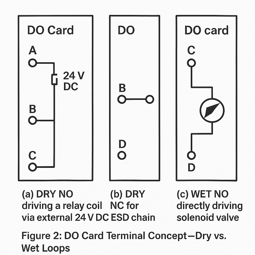
2) Digital Output (DO) wiring—dry vs. wet contacts
2.1 Definitions (plain English)
DRY NO (Dry, Normally Open): A potential-free (no internal power) contact that is open in normal state and closes on action to pass a signal.
DRY NC (Dry, Normally Closed): A potential-free contact that is closed in normal state and opens on action.
WET NO (Wet, Normally Open): A powered output (has its own supply, e.g., 24 VDC or AC mains through the I/O module) that is open in normal state and closes on action to directly drive a load (e.g., a solenoid coil).
2.2 Selection guide (fail-safe thinking)
Use fail-safe as your first lens: if the instrument or cable fails open/loses power, what should the plant do?
| Use case | Recommended contact | Normal state | Action state | Rationale |
|---|---|---|---|---|
| High-temperature / high-pressure trip (must stop safely on failure) | DRY NC | Closed | Opens on trip | If the loop breaks or card loses power, it opens → trip stays safe (de-energized-to-trip) |
| Low-level alarm (avoid false alarms on failure) | DRY NO | Open | Closes on alarm | If the loop breaks, it remains open → avoids spurious alarm |
| Remote start command | DRY NO | Open | Closes to start | Prevents unintended starts on wire short or idle noise |
| Emergency stop (ESD) | DRY NC | Closed | Opens to stop | Break = stop; the safest behavior |
Rule of thumb:
Processes that must shut down on loss of power → design de-energized-to-trip using NC safety chains.
Commands that should not occur accidentally (e.g., start/open) → NO paths.
2.3 Typical terminal mapping patterns
Most DO cards provide terminal pairs or quads (often labeled A/B/C/D). Patterns vary by vendor and card type, but the common conventions are:
Dry contact mode (relay output inside the card):
A–B: one relay contact (NO or NC, configurable or fixed by card type)
C–D: the complementary contact (e.g., the other throw or an independent channel)
Wet output mode (transistor/triac):
A: + supply out, C: switched leg to load (or vice versa)
B/D: returns or separate channels, depending on card
Always confirm the exact pole/throw and current rating in the card datasheet before wiring. If you are wiring Start/Stop pushbutton signals to a motor loop, a common pattern is Start on one pair (e.g., A–B), Stop on another (e.g., A–D)—but verify the module’s internal schematic first.
3) Digital Input (DI) wiring—what to put on A/B
DI cards read dry contacts from field devices such as valve limit switches (open/closed), level switches, motor run/fault contacts.
Wire the two wires of the dry contact to the DI channel’s A/B (or “+ / –”) terminals.
If the DI provides internal 24 VDC and a pull-up/pull-down, follow the manufacturer’s diagram (e.g., A = 24 V sense, B = return through the contact).
For field contacts exposed to noise or long runs, use:
Twisted pair,
Shielding terminated at one end (typically cabinet end),
Debounce or input filtering settings in the controller if supported.

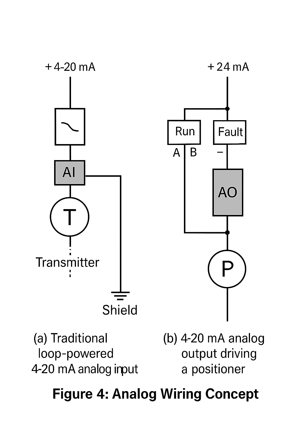
4) AI/AO quick notes
AI (Analog Input): 4–20 mA loops; choose active (card supplies power) vs. passive (loop-powered transmitter supplies power) correctly. Avoid ground loops; keep shields single-ended.
AO (Analog Output): 4–20 mA to positioners/VFDs; confirm I-to-P or positioner input impedance, and isolation. For analog valve position feedback, route back to AI as a separate loop.
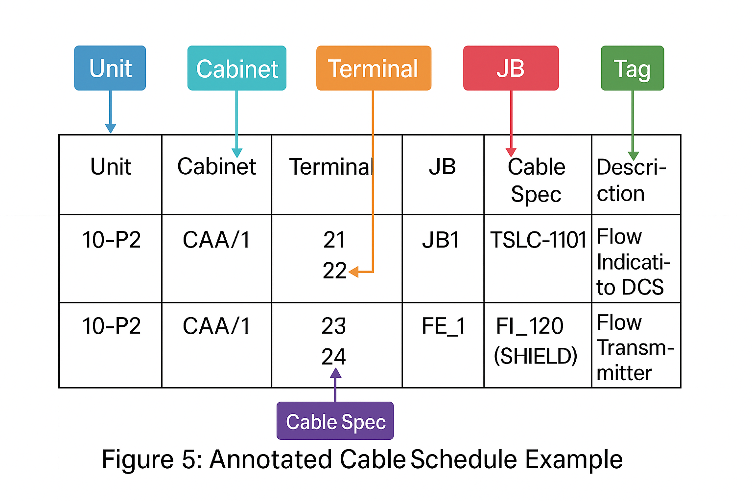
5) Reading the cable schedule “at a glance”
A typical cable schedule line encodes unit/sub-unit, cabinet name, card face/slot, terminal numbers, junction box (JB), branch cable, core IDs, shield/ground, and destination tag. After you’ve seen a few, the pattern becomes fast to parse:
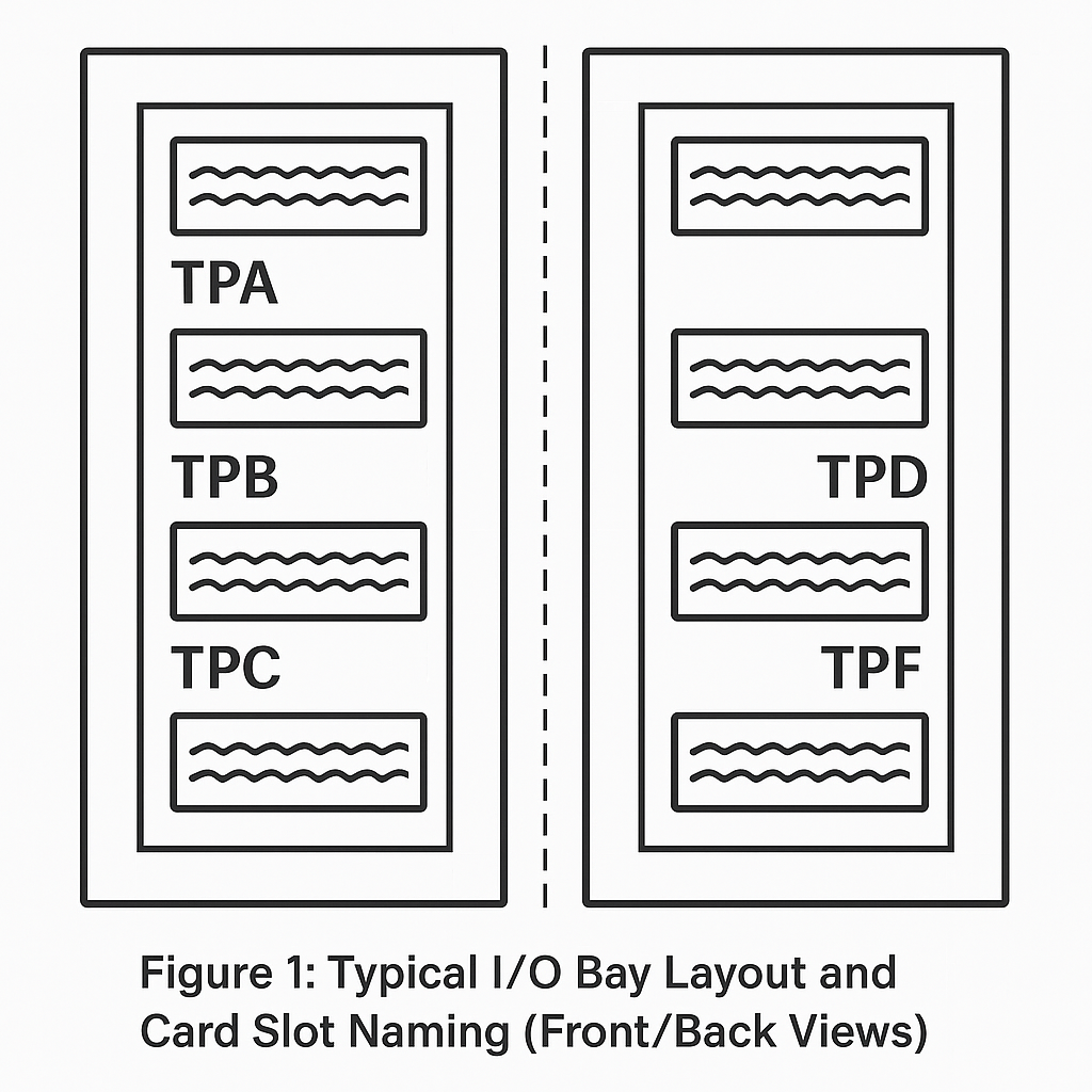
Area/Unit & Instrument Bay — e.g.,
02-DCS-RAL-02→ Unit 02, DCS, Digital Input cabinet, cabinet #02.Card face/slot naming — cabinets often label front (F) as TPA/TPB/TPC by row, rear (R) as TPD/TPE/TPF. The “3rd card in TPB” narrows to a single terminal block quickly.
Main cable / branch cable — e.g.,
12×2×1.5means 12 pairs of 1.5 mm² cores; branch numbers map to JB terminals.Terminal pairs — e.g.,
31–32,34–35indicate A/B pairs; scattered numbers (e.g.,33/36/39/42/45) may be common returns/grounds.Signal tags — look for
LT/TV/UA/UL/STR/STP/SIC-style tags to decode level/temperature, run/alarm, start/stop, or VFD status conventions.
Fast checklist when reading a line:
✅ Which unit/cabinet/row?
✅ Which card/slot/face (F vs. R)?
✅ Which terminal pair (A/B) and is there a dedicated return?
✅ From which JB terminal to which cabinet terminal?
✅ What is the signal tag and I/O type (DI/DO/AI/AO)?
6) Commissioning & safety checklist
Fail-safe verified: Trip loops behave correctly on wire break and card power loss.
Contact logic: DI sense (NO/NC) matches P&ID and Cause-&-Effect matrix.
Load ratings: DO (dry/wet) contact ratings exceed coil inrush and steady current; add interposing relays if needed.
Shielding & grounding: One-end shield termination; segregation of protective earth (PE) vs. instrument ground (SG) where required.
Labeling: Cable ferrules and terminal markers match the schedule; JB terminal numbers double-checked.
Loop test records: As-built redlines captured for any deviations.
7) Typical pitfalls (and how to avoid them)
Wrong dry/wet assumption: Confirm whether the DO is powered. Never assume the card is a relay.
Start/Stop crossed: Keep start on NO logic and stop/ESD on NC logic chains.
Shared commons miswired: On multi-channel cards, ensure the correct common is used for each channel.
Shield grounded at both ends: Leads to ground loops—use single-point shield grounding.
Analog loop polarity errors: AO/AI 4–20 mA loops are polarity sensitive; reverse wiring will read 0 mA.

8) Conclusion
The fastest path to reliable I/O is to (1) apply fail-safe logic first, (2) wire DOs/DI correctly for the intended behavior (energized-to-run vs. de-energized-to-trip), and (3) learn to decode the cable schedule so you can find the exact terminals without hunting. Although cabinet codes and terminal labels differ across vendors, the principles and patterns above are broadly applicable to mainstream DCS/SIS platforms.