1. Introduction
Industrial thermocouples often operate in harsh environments characterized by high temperatures, dust-laden gases, corrosive atmospheres, and mechanical impact. Under such conditions, premature failure can occur due to wear, corrosion, or thermal shock. Shaped refractory bricks provide a physical barrier and environmental isolation for the thermocouple sheath and sensing junction. By tailoring the brick geometry and selecting a suitable refractory material, service life is extended and temperature measurements remain accurate.
2. Core Protective Functions of Shaped Bricks
2.1 High-Temperature Isolation and Thermal Shock Buffering
Shaped bricks (e.g., high-alumina or corundum) can directly contact hot zones while isolating the thermocouple from extreme heat. Their low thermal conductivity moderates temperature transients, reducing thermal shock to the thermocouple materials.
2.2 Mechanical Wear and Impact Protection
In furnaces with abrasive dust or particle flux (e.g., cement kilns, metallurgical furnaces), the brick acts as a sacrificial shield, absorbing particle erosion and direct impact, thereby minimizing wear on the protective sheath.
2.3 Corrosive Media Isolation
Depending on the atmosphere (acidic or alkaline), selected refractory materials can block corrosive gases and slags from contacting the thermocouple, preventing pitting and perforation of the sheath.
2.4 Positioning and Stable Support
Custom geometries (stepped, L-shaped, or bored bricks) allow precise positioning and stable support. This maintains a repeatable insertion depth and measurement point despite vibration and process disturbances.
3. Material Selection Based on Operating Conditions
Material selection should match maximum continuous temperature, chemical environment, and expected particle load. Typical options are summarized below:
| Material Type | Temperature Range (°C) | Key Features | Typical Applications |
|---|---|---|---|
| Fireclay Brick | 1300–1500 | Low cost; good thermal shock resistance | Medium-temperature kilns |
| High Alumina Brick (Al₂O₃ 60–80%) | 1500–1700 | High temperature and abrasion resistance | Metallurgical furnaces; glass kilns |
| Corundum Brick (Al₂O₃ ≥ 90%) | 1700–2000 | Excellent high-temperature and acid resistance | Aerospace/heat-treatment furnaces |
| Magnesia Brick | 1600–1800 | Strong resistance to alkaline slags | Steelmaking converters; alkaline kilns |
Note: Always verify refractory compatibility with the specific gas composition (e.g., SOx, alkali vapors) and slag chemistry in your process.
4. Installation and Design Considerations
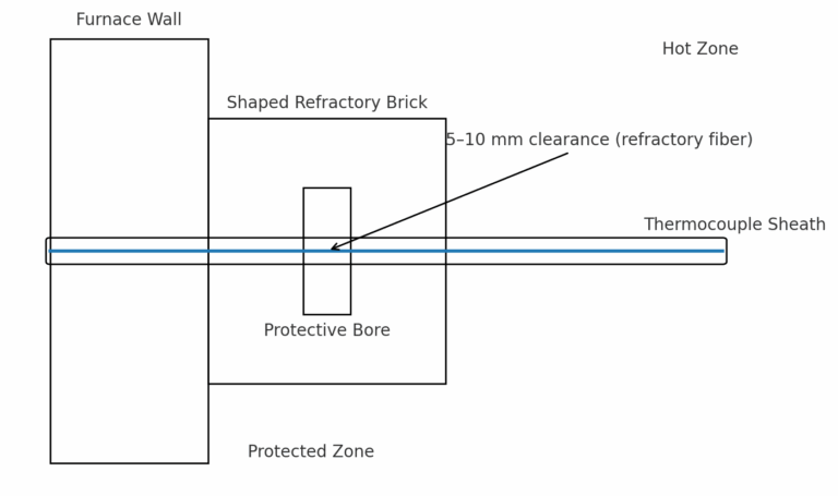
4.1 Shape Customization and Fit Clearance
Design the brick bore to match the thermocouple sheath diameter while reserving a 5–10 mm clearance around the sheath. Fill the clearance with refractory fiber to improve sealing and thermal stability without significantly delaying heat transfer.
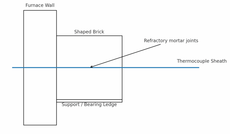
4.2 Masonry Stability
Bond the shaped brick to the furnace lining with refractory mortar to prevent hot gas or dust ingress through gaps. For vertical installations, include a support ledge or bracket beneath the brick to bear long-term weight and avoid slippage.
4.3 Thermal Response Balance
Overly thick bricks increase thermal lag, while overly thin bricks reduce protection. As a general starting point, a brick thickness of 10–30 mm is used and then optimized based on process dynamics and accuracy needs.
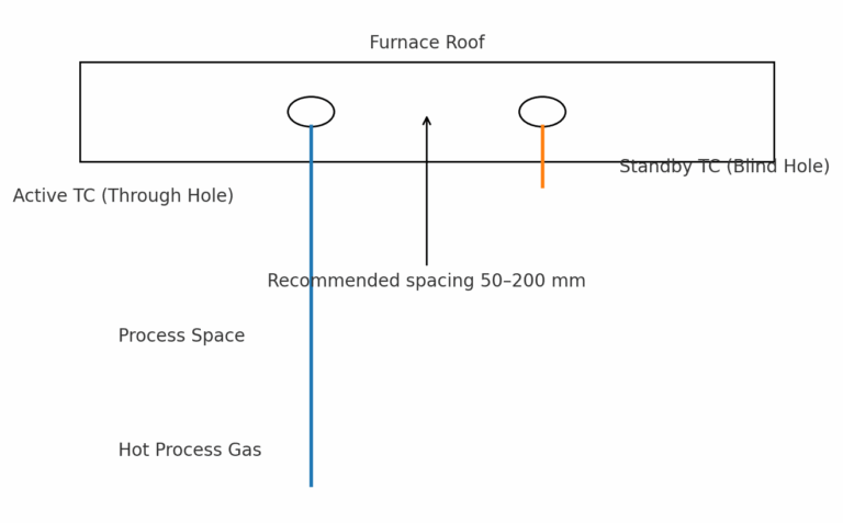
4.4 Dual-Hole Arrangement for Redundancy (Optional)
To maintain continuous temperature indication during maintenance or failure, some installations drill two holes at the same roof location—one through hole for the active thermocouple and one blind hole for a standby unit. This enables quick switchover without losing the measurement point.
5. Operation and Maintenance
5.1 Regular Inspection for Wear and Cracks
Depending on process severity, plan shutdown inspections every 3–6 months. Replace shaped bricks when significant erosion occurs (e.g., thickness loss > 30%), or when cracks/spalling are observed near the bore or load-bearing surfaces.
5.2 Avoid Rapid Thermal Cycling
During start-up and shutdown, limit temperature ramp rates (e.g., ≤ 50 °C/h) to reduce thermal stress and prevent cracking, especially for dense, brittle refractories.
5.3 Cleaning and Gap Maintenance
Keep the clearance region free of accumulated dust or slag. Clean and re-pack with refractory fiber if deposits are observed, to maintain heat transfer and avoid local overheating.
6. Quick-Reference Parameters
| Parameter | Recommended Starting Value |
|---|---|
| Clearance around sheath | 5–10 mm (packed with refractory fiber) |
| Brick thickness | 10–30 mm (optimize per process dynamics) |
| Inspection interval | Every 3–6 months (adjust per severity) |
| Temperature ramp rate | ≤ 50 °C/h during start-up/shutdown |
7. Summary
Shaped refractory bricks offer a robust protective solution for thermocouples operating in high-temperature, abrasive, or corrosive environments. By combining suitable materials with carefully engineered geometry, secure masonry, and disciplined maintenance, users can significantly extend sensor life and ensure reliable temperature measurement for closed-loop control and safety monitoring.