Correct installation of orifice plate flowmeters is crucial to ensuring measurement accuracy and long-term stable operation. The following sections provide a detailed procedure and key considerations for installation.
1. Pre-Installation Preparation
1.1 Verify Specifications and Model Selection
Confirm that the orifice plate’s specifications (e.g., nominal diameter, pressure rating, bore size, flow direction mark) meet the project design requirements.
Pay special attention to the orientation of the bore: the sharp-edged side should face upstream (the fluid inlet side).
Inspect the orifice plate surface for damage, corrosion, or deformation. Make sure the edge of the orifice is free from burrs or wear. Clean or replace it if necessary.
1.2 Pipework Preparation
Thoroughly clean the inside of the pipeline to remove welding slag, rust, and debris, preventing blockages or abrasion to the orifice or impulse lines.
Check that the pipe’s internal diameter matches the nominal diameter of the flowmeter. If reducers are present, ensure a smooth transition to avoid flow disturbances.
1.3 Select Installation Location
Choose a location with sufficient straight pipe runs upstream and downstream to ensure a stable flow profile:
Upstream: ≥10D (D = pipe inner diameter); ≥20D if near disturbances like elbows or valves.
Downstream: ≥5D.
Avoid installing the orifice plate at the highest point (for liquids) or lowest point (for gases) of the pipeline to prevent air or liquid accumulation.

2. Installation Direction and Mounting
2.1 Correct Installation Direction
The arrow or “UPSTREAM” marking on the orifice plate must match the flow direction.
The sharp-edged side of the orifice must face upstream.
For horizontal pipes, install the orifice plate vertically to prevent uneven fluid distribution.
2.2 Flange Connection and Sealing
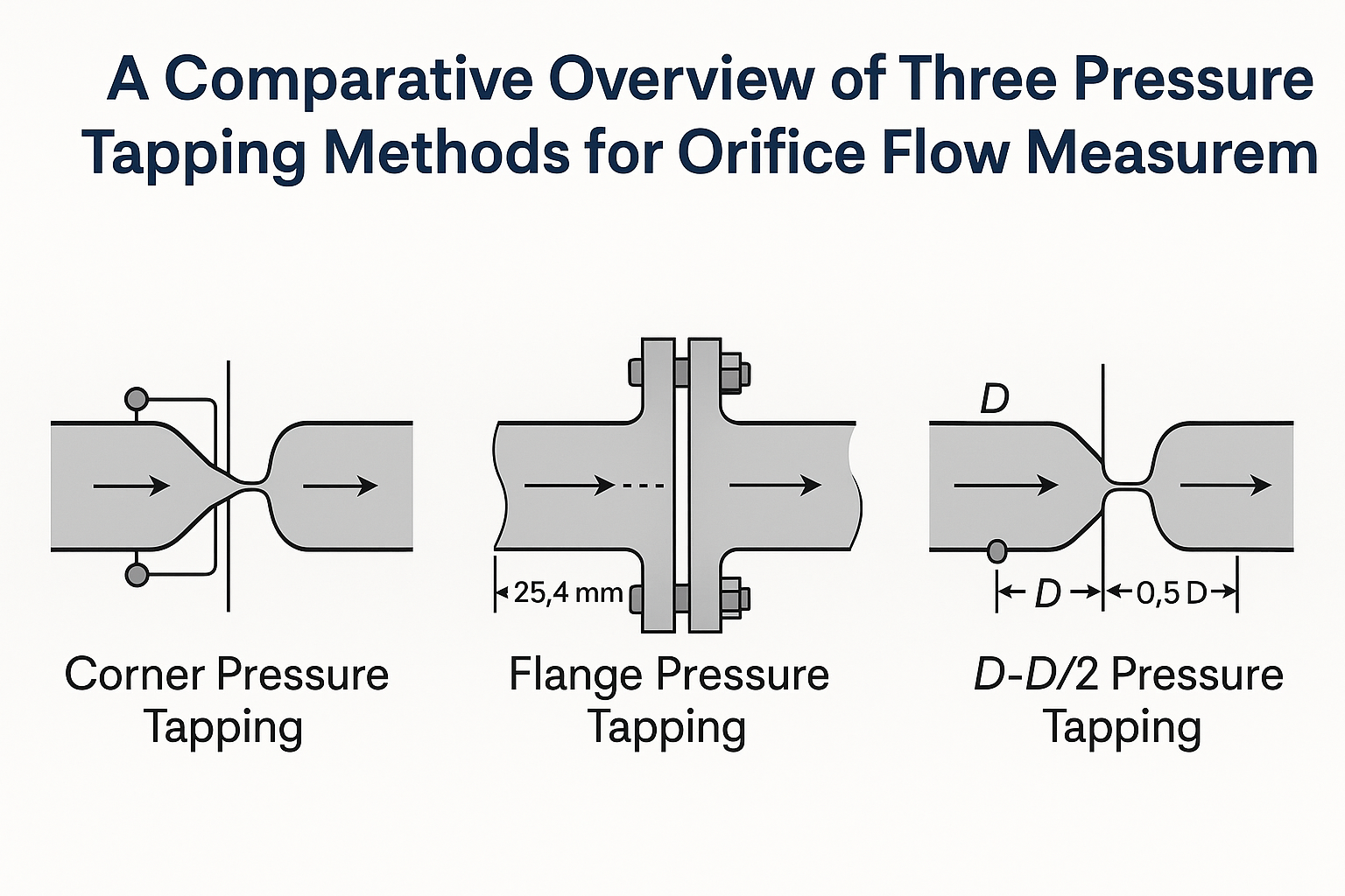
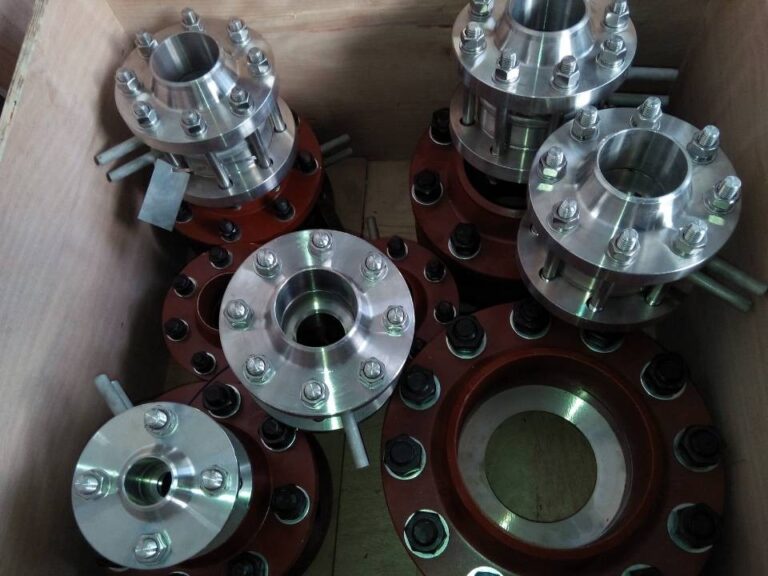
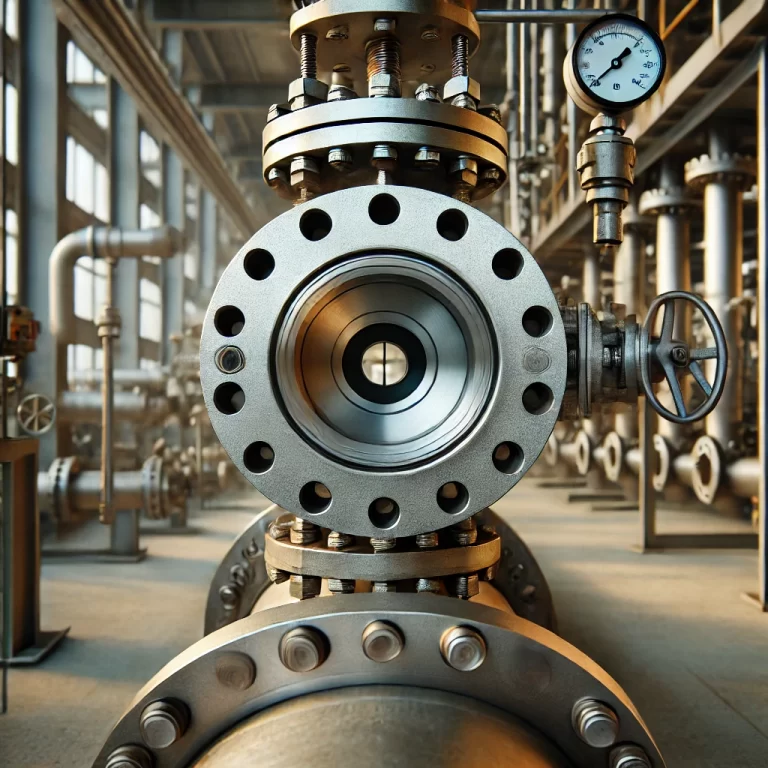
Use matched flanges with an inner diameter equal to the pipe’s inner diameter to prevent flow disturbance.
Place a sealing gasket (e.g., spiral wound gasket) between the flanges, ensuring that the gasket’s inner diameter is larger than the bore to avoid flow obstruction.
Tighten flange bolts symmetrically and evenly to prevent orifice deformation or leakage.
3. Impulse Line Installation
Impulse lines transmit differential pressure signals to measuring instruments. Their installation quality significantly affects measurement accuracy.
3.1 Material and Sizing
Choose corrosion-resistant materials compatible with the measured fluid (e.g., stainless steel for corrosive media).
Standard diameter: DN10–DN15; keep the length as short as possible (typically <50 meters) to reduce signal lag.
3.2 Routing and Slope Requirements
| Measurement Type | Routing Guideline |
|---|---|
| Liquid | Run impulse lines horizontally or slightly downward from the tapping point. If the pipe is above the instrument, maintain a downward slope ≥1:10. Install air vents at the highest point. |
| Gas | Run impulse lines horizontally or slightly upward. If the pipe is below the instrument, maintain an upward slope ≥1:10. Install drain valves at the lowest point. |
| Steam | Install condensate pots on both upstream and downstream impulse lines. Ensure equal height and apply thermal insulation. |
3.3 Anti-Clogging and Corrosion Protection
Use filters or isolators at the tapping points for fluids containing impurities.
For corrosive fluids, use corrosion-resistant impulse lines or fill them with isolation liquid.

4. Installation Tips for Different Media
4.1 Liquid Service
Install the orifice plate on the lower half of the pipe (angle 45°–90° to the horizontal) to avoid air pockets in the impulse lines.
Use air vents downstream if the fluid may produce gas bubbles (e.g., high-temperature liquids).
4.2 Gas Service
Install the orifice on the upper half of the pipe (angle 0°–45°) to prevent liquid condensation from entering impulse lines.
If the gas contains condensate, install drain valves at the lowest points of impulse lines.
4.3 Steam Service
Always install condensate pots with equal height on both sides.
Insulate impulse lines to prevent condensation.
Choose stable flow locations away from superheaters or pressure-reducing valves.
5. Post-Installation Inspection and Commissioning
5.1 Leak Test
Perform pressure testing (hydrostatic or pneumatic) after installation to verify sealing at flanges and impulse line joints.
5.2 Final Flow Direction and Straight Pipe Check
Recheck flow direction and confirm there are no upstream/downstream obstructions (e.g., valves or elbows).
Ensure the pipe inner walls are smooth and clean.
5.3 Instrument Connection and Calibration
Properly connect differential pressure transmitters or indicators.
Ensure good signal cable shielding to avoid electromagnetic interference.
Perform zero-point calibration and range setting. For critical applications, consider wet calibration with standard equipment.

6. Key Safety and Maintenance Notes
Never install or remove under pressure: Always depressurize the pipeline before handling the orifice plate to prevent injury.
Avoid mechanical damage: Handle the orifice plate gently. Never strike or drop it to avoid damaging the bore edge.
Labeling and Documentation: Mark the flow direction near the orifice and record installation date, calibration cycle, and related data for maintenance tracking.
By following these installation guidelines, you can minimize measurement errors and extend the service life of the orifice plate flowmeter. For special conditions (e.g., high pressure, high viscosity fluids), refer to the manufacturer’s manual or consult professional technicians.
