The proper arrangement of pressure, temperature, and flow instruments, along with valves, in a pipeline system is crucial for accurate measurement, efficient control, and safe operation. Incorrect placement can lead to measurement errors, inefficient system performance, and potential safety hazards. This article outlines the general guidelines and best practices for installing these instruments to ensure optimal performance.
General Arrangement Order
The typical sequence of installation for pressure, temperature, and flow instruments, along with valves, in a pipeline follows this order:
Upstream Valve (Isolation or Control Valve)
Pressure Measurement Device (Pressure Transmitter or Gauge)
Temperature Measurement Device (Temperature Sensor or Thermowell)
Flow Measurement Device (Flow Meter)
Downstream Valve (Regulating or Isolation Valve)
This arrangement ensures that instruments receive stable, undisturbed flow conditions, allowing for accurate measurement and control.
Detailed Placement Guidelines
1. Upstream Valve (Isolation or Control Valve)
Installed before pressure, temperature, and flow measuring instruments.
Helps control the process fluid before it reaches the measuring instruments.
Prevents fluctuations that may impact instrument readings.
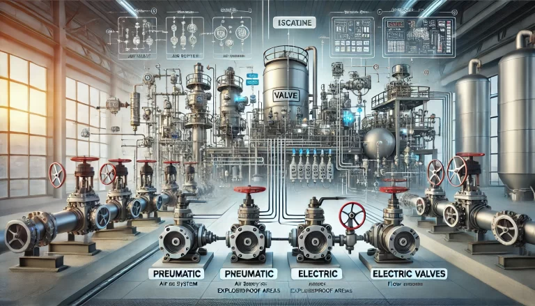
Can be a globe valve, gate valve, ball valve, or control valve, depending on the application.
2. Pressure Measurement (Pressure Transmitter or Gauge)
Typically located upstream of the flow meter, at a stable flow section.
Should be mounted on the pipe’s top or side for gas applications to avoid liquid accumulation.
For liquid applications, the pressure tap should be positioned at the lower section of the pipe to prevent gas trapping.
Avoid placing near bends, elbows, or valves to minimize turbulence effects.
3. Temperature Measurement (Thermocouple, RTD, or Thermowell)
Installed downstream of the pressure measurement device.
Inserted into a thermowell to protect the sensor from high pressures and mechanical damage.
Positioned at a location where the fluid is well-mixed and represents the actual process temperature.
For gases, it should be placed in a vertical pipe section to reduce heat conduction errors.
Avoid placing near heat sources, such as pumps, that may cause localized temperature variations.
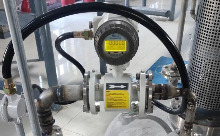
4. Flow Measurement (Flow Meter)
Installed downstream of pressure and temperature measuring devices to ensure accurate flow readings.
Requires sufficient straight pipe sections before and after the meter to reduce turbulence:
Typically, 10D upstream and 5D downstream (D = pipe diameter) is recommended.
Requirements vary by flow meter type:
Orifice Plate: 10D upstream, 5D downstream
Turbine Meter: 20D upstream, 10D downstream
Vortex Flow Meter: 10D upstream, 5D downstream
Electromagnetic Flow Meter: 5D upstream, 3D downstream
Should be installed in a fully filled pipeline for liquid applications to prevent inaccurate readings due to air pockets.
5. Downstream Valve (Regulating or Isolation Valve)
Located after the flow meter to ensure stable conditions during measurement.
Reduces flow fluctuations that can affect readings.
Typically used to regulate flow rates or isolate instruments for maintenance.
Special Considerations Based on Fluid Type
For Liquid Applications:
The pressure gauge should be installed at the lowest point to prevent air bubbles from affecting the measurement.
The temperature sensor should be deep enough into the fluid stream to ensure accurate readings.
Flow meters must be installed in a section where the pipeline is always filled to avoid cavitation or partial filling errors.
For Gas Applications:
Pressure sensors should be installed on the side or top of the pipe to avoid condensate buildup.
Temperature sensors should be positioned where the gas flow is uniform and well-mixed.
Flow meters should be installed away from heat exchangers, compressors, or turbulence-inducing components.
For Steam Applications:
Pressure transmitters should include a condensate pot to protect against high temperatures.
Temperature sensors should be installed in thermowells to prevent direct exposure to extreme heat.
Flow meters should be positioned in locations where steam quality remains consistent and free from excessive moisture.
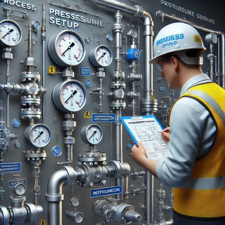
Typical Pipeline Instrumentation Setup
A simplified diagram representing the correct sequence of instruments in a pipeline:
→ Upstream Valve → Pressure Sensor → Temperature Sensor → Flow Meter → Downstream Valve →
This layout ensures that:
Pressure and temperature sensors provide accurate readings before the flow meter.
The flow meter operates under stable, controlled conditions.
Downstream regulation does not interfere with instrument readings.
Conclusion
Correct placement of pressure, temperature, and flow instruments, along with valves, in a pipeline is essential for accurate monitoring and efficient process control. By following best practices and considering the specific characteristics of the fluid, engineers can optimize system performance, enhance safety, and reduce maintenance costs. Proper instrumentation placement not only improves measurement accuracy but also extends the lifespan of equipment, ensuring a reliable and efficient operation.