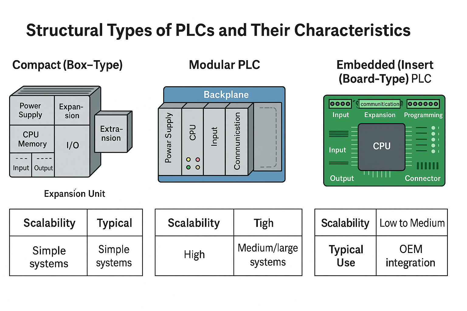
In programmable logic controller (PLC) applications, discrete logic control refers to the processing of binary signals—on/off, true/false—based on specific logical relationships. This document outlines three commonly used programming approaches: Basic Logic Design, Advanced Logic Design, and Engineering Design Methods.
1. Basic Logic Design Method
The basic logic design method uses simple logic operations (AND, OR, NOT) to establish relationships between input and output signals. It includes two major steps:
Logic Analysis: This process examines existing ladder diagrams to determine how current and historical inputs affect outputs. It helps identify the logic behind the control scheme.
Logic Synthesis: In contrast, logic synthesis creates ladder programs based on desired input-output behavior. It involves designing control algorithms and selecting appropriate basic PLC instructions.
🔹 Note: Logic synthesis is considered the inverse of logic analysis and often has multiple correct solutions. Because the logic theory is mature, optimized programming is achievable through careful instruction selection and resource planning.
While the basic method produces compact and rigorous code, it can become complex when managing numerous variables. Moreover, with the evolution of PLCs, advanced instructions are often more suitable for complex logic processing.
2. Advanced Logic Design Method
The advanced logic design method expands upon the basic logic framework by introducing more complex relationships and making full use of advanced PLC instructions. It applies the same logic analysis and synthesis techniques, but beyond traditional logic gates.
Two techniques are commonly used:
Flag Logic Design: Uses internal memory bits (flags) to track system states or transitions, simplifying complex interlocks.
Multibit Logic Design: Involves evaluating and manipulating grouped binary signals, enabling efficient control of multi-state devices.
This method offers flexibility and improved resource utilization but requires a deeper understanding of PLC instruction sets.
3. Engineering Design Method
Engineering design is a top-down approach that uses automatic control theory to analyze and build sequential control logic based on system behavior and task sequences. It focuses on how the system should operate in a step-by-step manner to fulfill process requirements.
3.1 Historical Perspective:
Distributed Control (Pre-PLC era): Widely used in metal-cutting machine tools, where each action is triggered by the feedback from the previous step.
Centralized Control: Mechanical methods like rotating camshafts distribute motion commands; each cam profile determines part movement. These systems lack feedback and require mechanical failsafes.
Hybrid Control: Modern machines employ software-based sequencing with feedback control. Each program segment executes based on confirmed completion of prior steps, ensuring both flexibility and safety.
When abstracted, these control mechanisms form the foundation for distributed, centralized, and hybrid control algorithms that are now realized through PLC software instead of hardware.
4. Recommended Approach
Based on practical experience, the engineering method offers the best balance of flexibility, safety, and clarity—especially in complex automation systems. It aligns closely with modern PLC capabilities and industrial demands.
Conclusion
Understanding and choosing the right logic programming method is essential for building efficient and reliable PLC control systems. While each approach has its strengths, the engineering design method is highly recommended for modern industrial applications.