This manual will assist you in installing, using, and maintaining your flow meter. It is your responsibility to make sure that all operators have access to adequate instructions about safely operating and maintenance procedures.
Operating Principle:
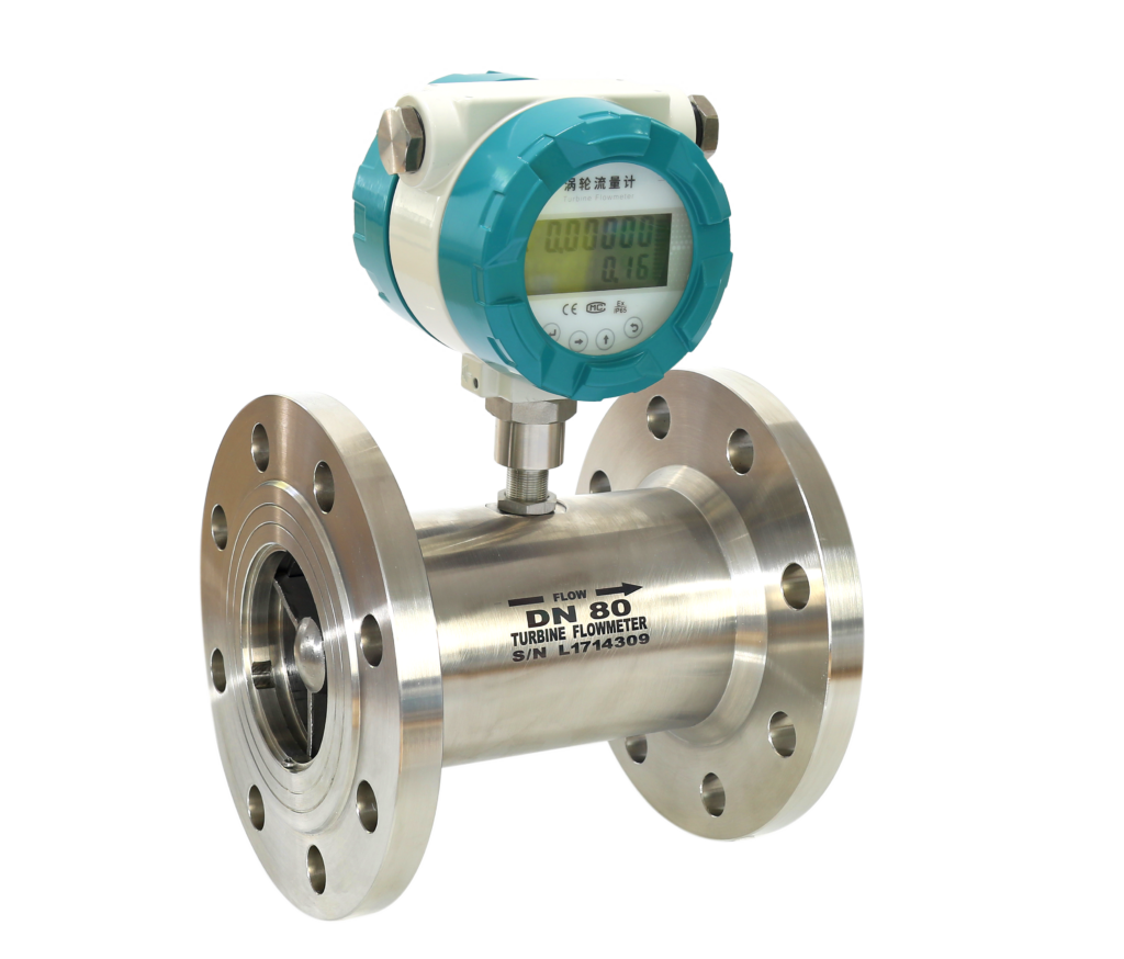
Liquid flows through the turbine housing causing an internal rotor to spin. As the rotor spins, an electrical signal is generated in the pickup coil. This signal is converted into engineering units (liters, cubic meters, gallons, etc.) on the local display where applicable. Optional accessory modules can be used to export the signal to other equipment.
Upon receipt, examine your meter for visible damage. The turbine is a precision measuring instrument and should be handled carefully. Remove the protective plugs and caps for a thorough inspection. If any items are damaged or missing, contact us.
Make sure the turbine flow model meets your specific needs. For your future reference, it might be useful to record this information on the nameplate in the manual in case it becomes unreadable on the turbine. Refer to the nameplate for your customized product’s specification.
. Cautions for Installation turbine type flow meter
4.1 Mounting Positions
• Pipes must be fully filled with liquids. It is essential that pipes remain fully filled at all times,
otherwise, flow rate indications may be affected and measurement errors may be caused
Avoid Air Bubbles. If air bubbles enter a measurement pipe, flow rate indications may be affected
and measurement errors may be caused
Avoid all pipe locations where the flow is pulsating, such as on the outlet side of the piston or
diaphragm pumps.
Avoid locations near equipment producing electrical interference such as electric motors,
transformers, variable frequency, etc.
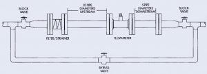
Install the turbine meter with enough room for future access for maintenance purposes.


