This manual will assist you in installing, using and maintaining your flow meter. It is your responsibility to make sure that all operators have access to adequate instructions about safe operating and maintenance procedure.
Operating Principle:
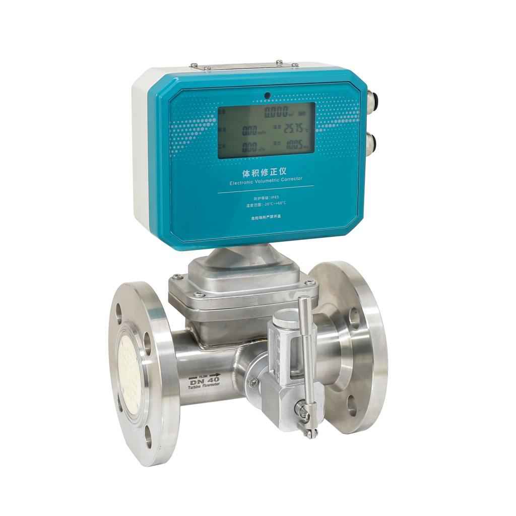
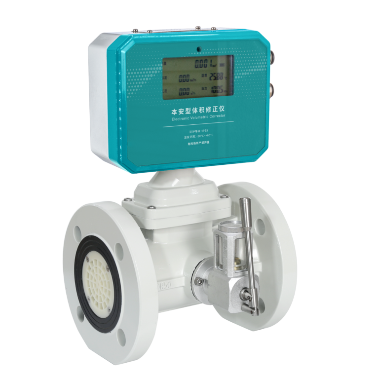
Gas flows through the turbine housing causing an internal rotor to spin. As the rotor spins, an electrical signal is generated in the pickup coil. This signal is converted into engineering units (liters, cubic meters, gallons etc.) on the local display where is applicable. Optional accessory modules can be used to export the signal to other equipment.
Upon receipt, examine your meter for visible damage. The turbine is a precision measuring instrument and should be handled carefully. Remove the protective plugs and caps for a thorough inspection. If any items are damaged or missing, contact
Make sure the turbine flow model meets your specific needs. For your future reference, it might be useful to record this information on nameplate in the manual in case it becomes unreadable on the turbine. Refer to the nameplate for your customized product’s specification.
1.0 SPECIFICATIONS
Performance
- Repeatability: ±0.2%
- Accuracy:
- Standard: ±1.5%
- Optional: ±1.0%
- (Comply to criteria: ISO9951)
Wetted Components
- Housing: Standard – Tungsten Carbide; Optional – 304, 316 Stainless Steel
- Bearings and Shaft: ABS (Corrosion Resist) or Aluminum-Alloy
- Rotor: ABS (Corrosion Resist) or Aluminum-Alloy
- Retaining Rings: 304 Stainless Steel
Output Signal (Where applicable)
- Sensor: Pulse signal (Low Level: ≤0.8V; High Level: ≥8V)
- Transmitter: 4 to 20mA DC current signal
Signal Transmission Distance
- ≤1,000m
Electrical Connections
- Basic Type: Hausman Connector or three-core cable
- Explosion Proof Type: ISOM20×1.5 Female
Explosion Proof Level
- Standard: None
- Optional: ExdIIBT6
Protection Level
- IP6
2.0 OPERATION CONDITIONS
Ambient:
- Temperature: -10°C to +55°C
- Pressure: 86 to 106 KPa
- Relative Humidity: 5% to 90%
Power Supply:
- Sensor: +12VDC (Optional: +24VDC)
- Transmitter: +24VDC
- Field Display Type B: Integral 3.2V Lithium Battery
- Field Display Type C: +24VDC
Fluid Temperature and Pressure:
- Temperature: 20°C to +80°C
- Pressure: Fluid pressure should be limited according to flange rating.
Measurable Flow Rate Range and Pressure Level (See Table 1)
Table 1: Measurable Flow Rate Range and Pressure Rating
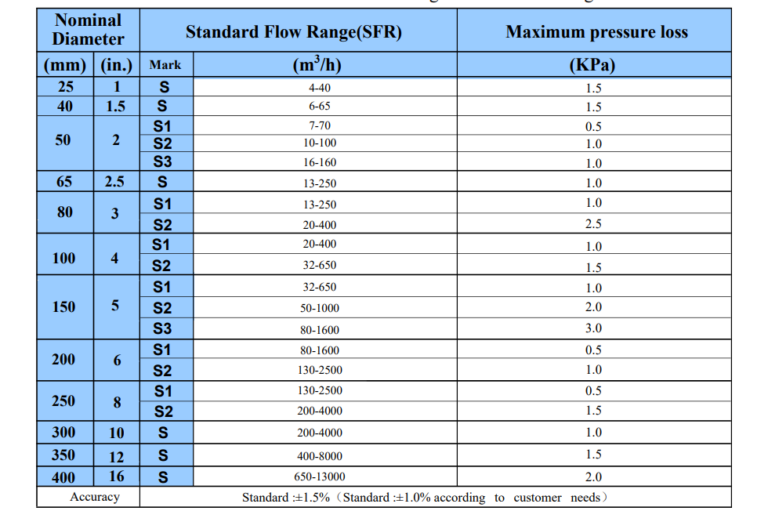
Accuracy:
- Standard: ±1.5% (Standard ±1.0% according to customer needs)
Illustrate:
- 1. The maximum pressure loss is the pressure loss when the flowmeter works at the maximum flow point. The medium is air, normal temperature, and normal pressure.
- 2. DN250~D400 is a non-oil filling structure.