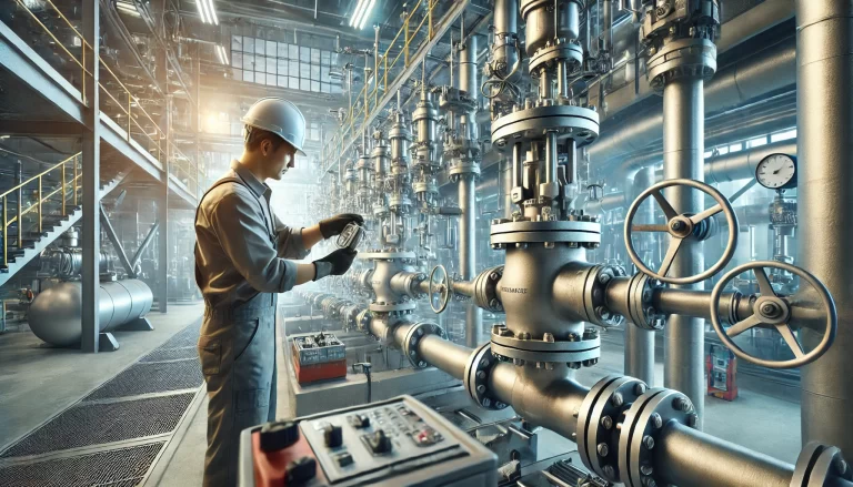
Introduction
Valves are essential components in chemical process systems, responsible for regulating the flow of gases, liquids, or slurries. The selection and placement of valves significantly impact plant safety, operational efficiency, equipment reliability, and maintenance costs. This guide outlines comprehensive principles for selecting and installing valves in chemical plants, with detailed consideration of fluid properties, operating conditions, valve functions, and installation environments.
1. Considerations Based on Fluid Properties
1.1 Physical State of Process Fluids
Gas Phase: Determine whether the gas is pure or mixed, whether it contains droplets or solid particles, and if any components are prone to condensation.
Liquid Phase: Consider volatility, dissolved gases (which may form a two-phase flow under pressure drop), presence of solid suspensions, viscosity, pour point, and freezing point.
1.2 Chemical Properties
Evaluate corrosiveness, toxicity, flammability, explosiveness, and the material compatibility of the fluid with valve components. These factors can dictate both material and structural requirements, possibly necessitating upgraded pipeline classification.
2. Operational Conditions
2.1 Normal and Abnormal Operations
Evaluate operating pressure and temperature during normal and start-up/shutdown conditions. For example, the valve at a pump outlet must withstand the pump’s maximum shut-off pressure.
2.2 Operating Frequency and System Pressure Drop
High Frequency Use: Consider valves with high wear resistance or use dual-valve arrangements for frequent operation.
Low Frequency Use: Ensure the valve does not stick over time.
Pressure Drop Constraints: For minimal allowable pressure drop, use low-resistance valves like gate or straight-through ball valves. For flow control, use valves with higher inherent pressure drop (e.g., globe valves).
2.3 Environmental Conditions
In cold climates, avoid using cast iron for outdoor installations of chemical lines; use cast steel or stainless steel instead.
3. Valve Functional Categories
3.1 Shut-Off Valves
Use gate, ball, or plug valves for full shut-off. For rapid shut-off, plug, ball, or butterfly valves are preferred.
3.2 Flow Direction Change
L-type and T-type three-way ball or plug valves allow quick direction change, reducing installation footprint.
3.3 Flow Regulation
Globe, plunger, and needle valves are ideal for fine-tuning. For large flow ranges, use throttling or butterfly valves.
3.4 Non-Return (Check Valves)
Install check valves to prevent backflow.
3.5 Special-Purpose Valves
Use valves with jackets, drains, bypasses, or purge ports depending on specific process needs.
4. Actuation and Control Mechanisms
4.1 Manual Operation
Handwheels are standard. For remote or inaccessible areas, use chain wheels or extended handles.
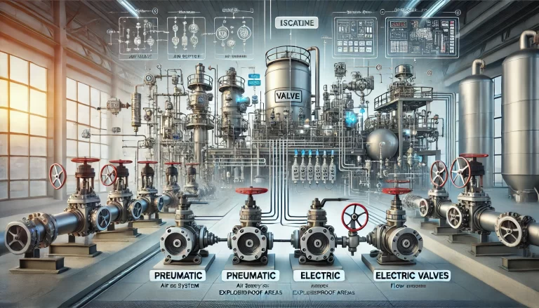
Large valves may require electric motors. Explosion-proof motors are mandatory in hazardous zones.
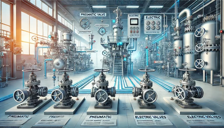
4.2 Remote Actuation
Actuation options include pneumatic, hydraulic, and electric (solenoid or motor-driven). Choose based on available utilities and control requirements.
5. Characteristics and Applications of Valve Types
5.1 Gate Valves
Low flow resistance, suitable for on/off service in large sizes and wide temperature/pressure ranges. Use open-stem types for visibility of valve status.
5.2 Globe Valves
Excellent for throttling, but higher pressure drop. Not suitable for suspensions. Limited to DN150-200.
5.3 Plug, Plunger, and Ball Valves
Quick operation, low pressure drop, suitable for slurries or viscous fluids. Easily adapted for automation.
5.4 Butterfly Valves
Ideal for large flow control with moderate pressure/temperature. Use triple-offset types for high-performance needs.
5.5 Check Valves
Prevent reverse flow. Types include swing, lift, and ball check valves. Choose based on orientation and size.
5.6 Diaphragm and Pinch Valves
Fluids contact only the membrane or hose, ideal for corrosive or viscous fluids.
6. Valve Installation Guidelines
6.1 Boundary Isolation Valves
Install shut-off valves at unit boundaries except for vent lines, non-critical utilities, and unmeasured service lines.
6.2 Root Valves
Install close to main pipelines to enable localized isolation during maintenance or to conserve energy.
6.3 Pump Outlet Valves and Check Valves
Use check valves to prevent reverse flow and water hammer. Choose swing type for DN>50 and lift type for DN<50. Install horizontal swing check valves DN>80 to reduce impact.
6.4 Control Valve Bypass Configuration
Install bypass lines to allow manual flow control during maintenance. Use globe valves (or gate valves if DN>200). Ensure layout avoids stress on the control valve.
6.5 Normally Open and Normally Closed Valves
Define valve status clearly. Use locks or seals to prevent unauthorized operation, especially in emergency isolation or interlock systems.
6.6 Air-Open vs. Air-Close Control Valves
Select based on process safety: air-to-close valves shut upon air failure to stop feed or heat; air-to-open valves ensure drain or venting during failure.
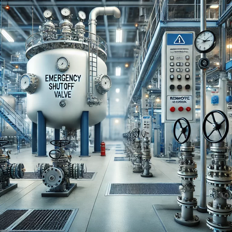
6.7 Double Block Valves
For toxic, flammable, or high-pressure fluids, install two isolation valves with a bleed valve in between. Use especially on sampling lines, LPG, hydrogen systems, and hazardous waste drains.
Conclusion
Correct valve selection and installation are vital for ensuring the safety, reliability, and efficiency of chemical processing systems. This guide presents structured and practical principles to aid engineers in designing robust valve systems tailored to diverse industrial requirements.