In the field of industrial flow measurement, differential pressure flowmeters are widely used due to their simple structure and durability. Among them, the segmental orifice flowmeter, as a special throttling device, shows unique advantages when dealing with dirty media containing bubbles, solid particles, or easily crystallizable substances. This article delves into the working principle, advantages, disadvantages, and key installation considerations of segmental orifice flowmeters.
1. Working Principle
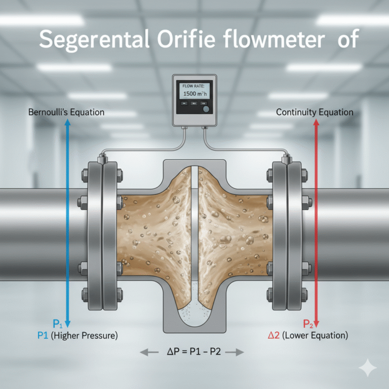
The segmental orifice flowmeter operates based on the same physical principles as the standard orifice plate—Bernoulli’s equation and the continuity equation for fluids. The core component is a throttling plate with a crescent-shaped (semicircular) opening installed between two pipeline flanges. When the fluid flows through the segmental orifice, the flow stream experiences local contraction, resulting in an increase in flow velocity.
The opening of the segmental orifice is located at the bottom or top of the pipeline, specifically designed to allow impurities, bubbles, or slurry in the measured medium to pass through smoothly, preventing accumulation before the throttling element. This is the key difference between the segmental orifice and the standard orifice plate.
Throttling Effect: When the fluid passes through the segmental orifice, the cross-sectional area suddenly decreases, converting part of the static pressure energy into dynamic energy, which increases the flow velocity.
Pressure Difference Generation: The increase in flow velocity leads to higher static pressure (P1) upstream of the segmental orifice and lower static pressure (P2) downstream. The pressure difference (ΔP = P1 – P2) is called the differential pressure.
Flow Calculation: According to Bernoulli’s equation, this pressure difference is proportional to the square of the flow velocity and, by extension, the square of the volumetric flow rate. By measuring this differential pressure and incorporating the fluid’s density, temperature, pressure, and the orifice’s opening size, an accurate flow rate can be calculated using a flow integrator.
2. Advantages and Disadvantages
Advantages:
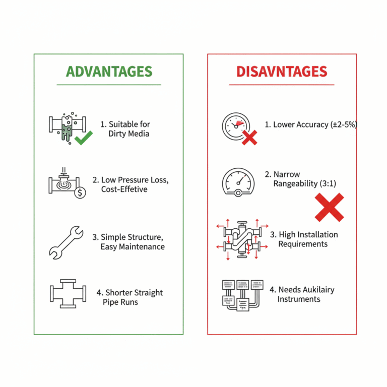
Suitable for Dirty Media: This is its primary advantage. It can easily measure fluids containing solid particles, bubbles, suspended solids, or substances prone to crystallization or sedimentation, such as coal gas, slurry, wastewater, and chemical raw materials.
Low Pressure Loss: Compared to other throttling devices, the segmental orifice generates relatively low permanent pressure loss, helping to reduce long-term operational energy consumption.
Simple Structure, Low Cost: Compared to complex throttling devices like venturi tubes, it has a simple structure, making it inexpensive to manufacture, install, and maintain.
No Need for Long Straight Pipe Segments: While some straight pipe sections are still required, the segmental orifice generally needs shorter straight pipe sections compared to standard orifice plates.
Wear Resistance: Due to its opening shape, solid particles in the fluid are less likely to cause concentrated wear on the edges of the throttling plate.
Disadvantages:
Relatively Low Accuracy: Due to the unstable flow conditions and complexity of the dirty media, the overall measurement accuracy is usually lower than that of standard orifice plates, typically around ±2% ~ ±5%.
Narrow Rangeability: Since the pressure difference is proportional to the square of the flow rate, the differential pressure signal is small at low flow rates, making it difficult to measure accurately. Therefore, the rangeability (the ratio of maximum flow rate to minimum flow rate) is generally narrow, usually around 3:1.
High Installation Requirements: The installation direction and pressure tapping position must be precise; otherwise, large errors will be introduced.
Needs Auxiliary Instruments: It must be used in conjunction with a differential pressure transmitter, pressure/temperature compensation instruments, and flow integrators, making the system relatively complex.
3. Installation Considerations
The performance of the segmental orifice flowmeter is highly dependent on correct installation. Any errors in installation could lead to measurement failure or significant errors.
Installation Direction:
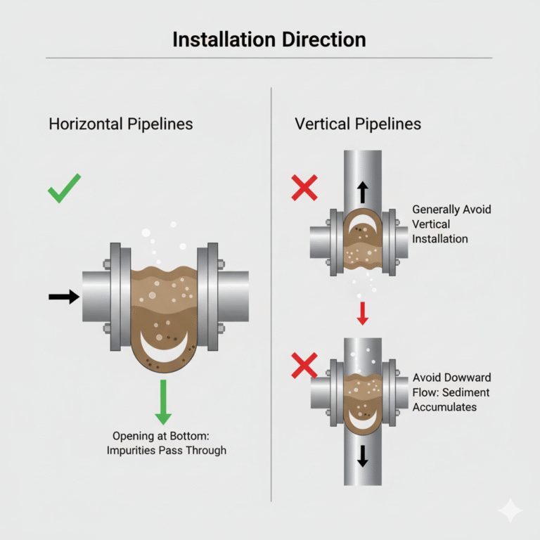
Horizontal Pipelines: This is the most common installation method. The opening of the segmental orifice must be positioned at the lower half of the pipeline, with the “crescent opening facing down.” This ensures that bubbles move upwards, and solid impurities or slurry settle at the bottom of the pipeline, flowing smoothly through the segmental opening without clogging.
Vertical Pipelines: This should generally be avoided. If necessary, ensure the flow moves from bottom to top.
Pressure Tapping Method:
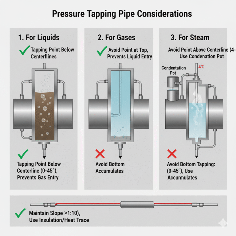
For liquid media, to prevent gas and sediment from entering the pressure tapping pipe, the tapping point should be located below the horizontal centerline of the pipeline and form a 0°–45° angle with it. It is typically recommended to install it at the horizontal centerline.
For gas media, the tapping point should be located at the top of the pipeline to prevent liquids and debris from entering.
For steam media, ensure that the measurement pipe is filled with condensate, so the tapping point should be above the horizontal centerline, forming a 0°–45° angle. It is usually installed at the horizontal centerline, with a condensation pot at the tapping valve group.
Straight Pipe Segment Requirements:
To ensure that the fluid forms a fully developed turbulent velocity profile before passing through the throttling element, sufficient straight pipe segments are required before and after the segmental orifice.
The upstream straight pipe typically requires 10D to 20D (D is the pipe diameter).
The downstream straight pipe usually requires around 5D.
The inner surface of the pipe near the segmental orifice should be smooth, clean, and free of protrusions (e.g., gaskets, weld seams).
Pipe Alignment:
The inner diameter of the pipeline where the segmental orifice is installed must match the design diameter used in the calculations. During installation, the centerline of the segmental orifice must be perfectly concentric with the pipeline centerline. Any misalignment could lead to unpredictable measurement errors.
Pressure Tapping Pipe:
The tapping pipe should be kept as short as possible and maintain a certain slope (typically greater than 1:10) to ensure that gas bubbles (for liquids) or condensate (for gases) can smoothly drain or return.
In cold environments, insulation or heating cables should be used on the pressure tapping pipes to prevent the medium from solidifying.
Conclusion
The segmental orifice flowmeter offers an economical and effective solution to measure the flow of dirty or crystallizing media. Its ingenious design bypasses the limitations of standard orifice plates in such applications. However, its performance is highly dependent on proper installation. Adherence to key details such as installation direction, pressure tapping position, and straight pipe segment lengths is essential. When selecting and applying this flowmeter, it is crucial to fully understand the characteristics of the process media and strictly follow installation guidelines to ensure stable and reliable measurements.