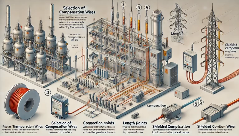
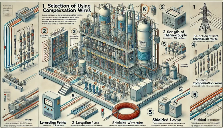
1. Selection of Compensation Wires
The selection of compensation wires must match the type of thermocouple being used and the specific application scenario. For example, K-type thermocouples should use K-type compensation wires. Additionally, the operating temperature range must be carefully considered.
- Common KX Compensation Wires: Suitable for operating temperatures between -20°C to 100°C.
- Extended Temperature Range Wires: Can operate within -25°C to 200°C.
- Accuracy Levels:
- Standard-grade error: ±2.5°C
- Precision-grade error: ±1.5°C
Common Mistake Example: Using compensation wires that do not match the thermocouple type can result in significant temperature measurement errors. Always verify the compatibility before installation.
2. Connection Points
When connecting compensation wires:
- Ensure the two connection points at the thermocouple terminal are as close as possible to each other. This minimizes temperature differences between them.
- Keep the temperature at the instrument connection terminals consistent.
- If the instrument cabinet has cooling fans, avoid direct airflow on the connection points, as this may cause temperature fluctuations.
Best Practice Example: In an industrial setting with significant air circulation, covering the connection points with an insulating shield can prevent unnecessary temperature variations.

3. Length of Use
Thermocouple signals are extremely weak, typically at the microvolt level. Long wire distances can cause:
- Signal Attenuation: Reducing the accuracy of temperature readings.
- Interference from Electrical Noise: External high-power lines can distort the signal.
Recommended Practice:
- Keep the compensation wire length under 15 meters for optimal performance.
- If the distance exceeds 15 meters, use a temperature transmitter to convert the thermocouple signal into a DC current signal. DC signals have stronger resistance to interference and can maintain accuracy over longer distances.
Example Scenario: In a factory setup where compensation wires need to run 30 meters, using a temperature transmitter can prevent inconsistent readings caused by signal degradation.
4. Wiring Layout
Compensation wires must be carefully routed to minimize interference:
- Keep them away from power lines and other sources of electromagnetic interference.
- When crossing power lines is unavoidable, use a perpendicular crossing instead of running them parallel.
Example of Poor Layout: Running compensation wires alongside high-voltage cables for extended distances can cause severe signal noise.
Best Practice Tip: Use dedicated cable trays or conduits for compensation wires to isolate them from power cables.
5. Shielded Compensation Wires
In environments with significant electrical noise, using shielded compensation wires can greatly enhance signal stability.
Key Requirements:
- The shielding layer must be properly grounded to effectively block interference.
- Improper grounding can cause the shielding layer to act as an antenna, amplifying interference instead of reducing it.
Example: In a power plant control room with high-frequency equipment nearby, a properly grounded shielded compensation wire system ensures accurate temperature measurements.
6. Common Mistakes and Troubleshooting
- Mistake 1: Using mismatched thermocouple and compensation wire types.
- Solution: Double-check the thermocouple type before selecting compensation wires.
- Mistake 2: Inconsistent temperatures at connection points.
- Solution: Keep connection points insulated and protected from airflow.
- Mistake 3: Excessive wire length without a temperature transmitter.
- Solution: Install a transmitter if the wire length exceeds 15 meters.

7. Summary and Key Takeaways
- Choose compensation wires that match your thermocouple type and operating conditions.
- Maintain consistency in connection point temperatures.
- Limit wire length to 15 meters or use a temperature transmitter beyond that distance.
- Avoid parallel routing with power lines; prefer perpendicular crossings.
- Use shielded compensation wires in noisy environments, and always ensure proper grounding.
By following these precautions, the performance and accuracy of thermocouple-based temperature measurement systems can be significantly improved, ensuring reliable and precise readings in industrial and laboratory environments.
