Background
In chemical plants and other process industries, it is common to encounter discrepancies between the output of field-mounted differential pressure (DP) transmitters and the values displayed or processed in the Distributed Control System (DCS). One of the most frequent causes is the inconsistent application of square root extraction (SQRT)—a method used to linearize flow measurements derived from differential pressure.
During the commissioning of a new unit, you might encounter scenarios where:
Square root is enabled only on the transmitter or only on the DCS, or
Both ends have square root disabled, leading to incorrect flow indication.
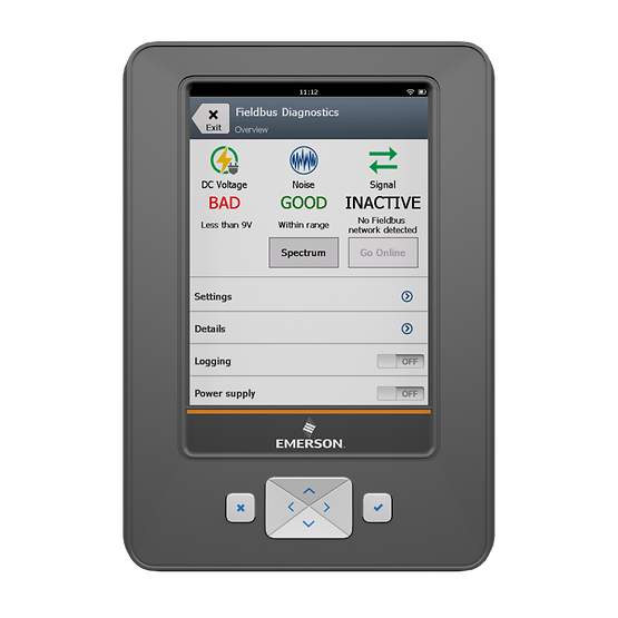
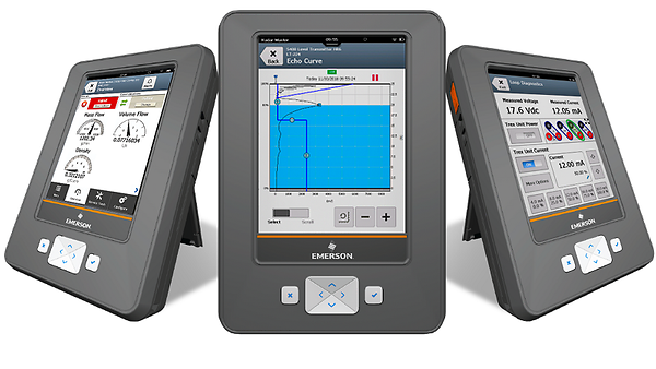
This guide walks through the step-by-step process of using Emerson’s TREX Field Communicator to configure a DP transmitter to apply square root output, thereby aligning with the DCS or correcting a mismatch.

Use Case Scenario
Recently, during site commissioning, we found that both the field transmitter and the DCS had square root disabled, which caused incorrect flow readings. The following procedure describes how we used the TREX device to access the DD file of the transmitter and configure it accordingly.
Step-by-Step Procedure
Step 1: Connect to the Transmitter and Read the DD File
Power on the TREX Field Communicator and connect it to the transmitter via the HART interface.
From the main menu, navigate to:
Device -> HART -> Read DD File
The communicator will read the device description (DD) file of the connected transmitter, allowing access to its configuration settings.
Step 2: Enter the Device Configuration Menu
Once connected, select:
Device Settings (Field Communicator)
You’ll see key live parameters such as:
Process Variable (e.g., -0.01614 kPa)
Output current (e.g., 3.957 mA)
LRV (Lower Range Value), URV (Upper Range Value)
Take note of these values for verification after configuration.
Step 3: Access Detailed Settings
From the settings menu, go to:
Detailed Configuration
This section includes advanced options including signal behavior, diagnostics, and analog output modes.

Step 4: Navigate to Signal Conditioning Settings
Select the menu:
Signal Conditioning or Display Condition (depending on the transmitter model)
Here, you will find configuration options for how the analog output is processed and displayed.
Step 5: Confirm Process Variable Range
Review the process variable range (e.g., 0.000 – 6.000 kPa).
This ensures that the configured output aligns with the expected input range of the DCS.
Step 6: Set Output Mode to Square Root (SQRT)
Locate the Analog Output (AO) setting.
Change the configuration from:
Linear AO, Linear Display
To:
Square Root AO, Square Root Display
This ensures both the signal being transmitted (AO) and the transmitter’s LCD display are using square root extraction.
⚠️ Important: Ensure that square root is not being simultaneously applied on the DCS side to avoid double square rooting, which will distort the measurement.
Step 7: Save and Exit
After setting the square root mode, save the configuration.
Exit the TREX menus and verify the live output and display values.
Confirm consistency with DCS readings during actual flow conditions.

Final Notes
By configuring the differential pressure transmitter to apply square root extraction directly via the TREX Field Communicator, we were able to resolve the inconsistency between the transmitter and the DCS system. This method is widely applicable across HART-enabled DP transmitters used in flow measurement systems.
To prevent similar issues in the future:
Define standard procedures for transmitter-DCS configuration alignment.
Document square root responsibility (transmitter-side vs. DCS-side) during design reviews.
Include these checks in commissioning checklists.
