Introduction
Electromagnetic Compatibility (EMC) is a critical aspect in the design and commissioning of electronic equipment. From industrial automation systems to household appliances and high-tech electronics, EMC issues can affect device performance, safety, and longevity. As the electromagnetic environment becomes increasingly complex, effective EMC design and interference troubleshooting have become essential skills for engineers.
This article, drawing from years of on-site experience, explores practical EMC techniques through real-world grounding and shielding cases. It focuses on how to properly handle shielded cables, connect analog signal shields, enhance communication cable immunity, and troubleshoot variable frequency drive (VFD) interference—ensuring device reliability and reducing system failures.

1. Understanding Shielded Cables
1.1 Definition and Application
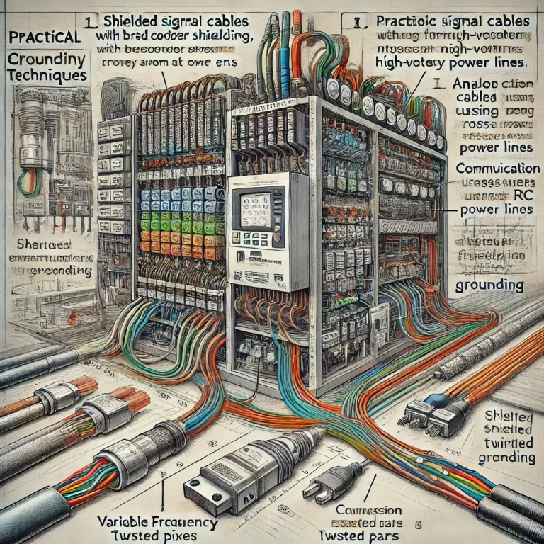
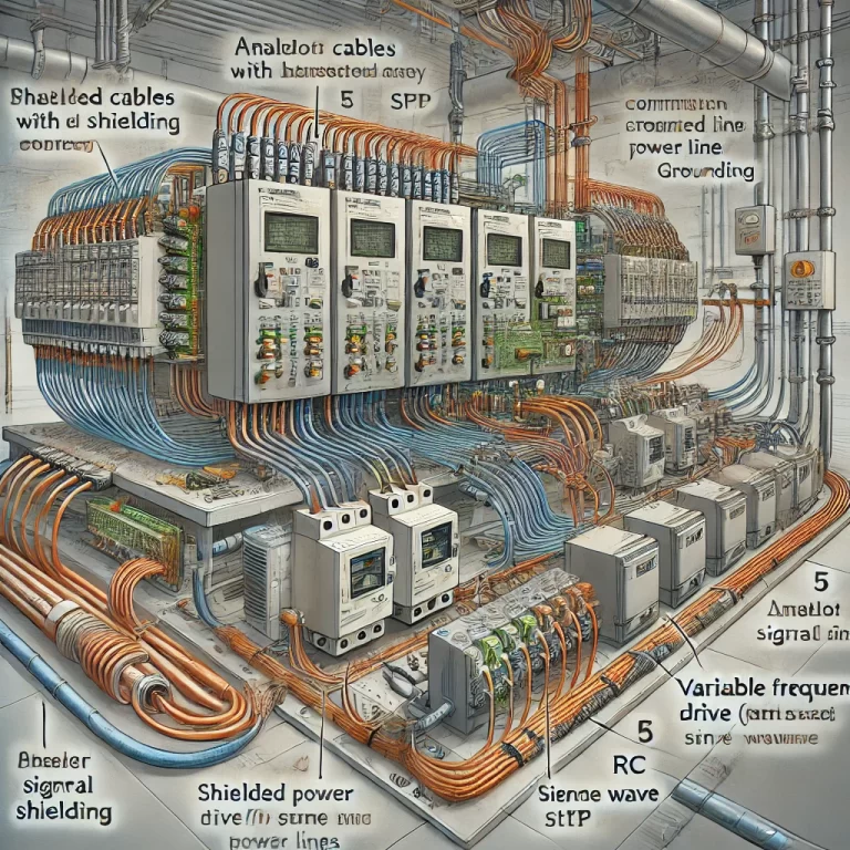
Shielded cables are designed to block electromagnetic interference (EMI) by incorporating a conductive layer—usually braided copper or foil—around the conductors. They are commonly used in power systems, control panels, communication equipment, and industrial automation.
1.2 Grounding Requirements for Shielded Cables
Proper grounding is vital. An ungrounded shield acts like an antenna, potentially worsening EMI. Practical issues include:
Poor Grounding: High ground resistance can compromise shield performance. In one project, poor grounding of a shielded cable allowed high-frequency noise to penetrate, leading to equipment failure.
Ground Noise: In older factories, long ground paths or unstable grounding systems can turn the shield into a noise source. We resolved such issues by shortening ground cables or using additional copper busbars to reinforce grounding.
1.3 Shielded Cable Routing
Effective routing is essential:
Avoid crossing power cables, especially high-voltage ones.
Maintain the shield’s continuity along the entire cable length.
A real-world example: a damaged shield crossing a high-current power line caused repeated system reboots due to EMI.
2. Analog Signal Shielding Techniques
2.1 Common Interference Sources
Analog signals from sensors and transmitters are highly susceptible to EMI, particularly in high-frequency industrial environments. Noise can distort readings or cause control system malfunctions.
2.2 Shield Connection Methods
Key practices include:
Double Shielding: Using cables with inner and outer shields for dual protection—inner for blocking external EMI, outer for preventing radiation.
Single-ended Grounding: Grounding the shield at one end (typically the controller side) prevents ground loop noise between different devices.
2.3 Layout and Routing Tips
Keep analog lines away from power cables.
Minimize cable length and avoid unnecessary bends.
These strategies significantly enhance signal integrity and measurement accuracy.

3. Improving Communication Cable Immunity
3.1 Common EMI Sources
Communication systems often face EMI from nearby power lines, switching devices, and VFDs. Symptoms include unstable links or data corruption.
3.2 Practical Countermeasures
Use Shielded Twisted Pair (STP): Particularly for long-distance or high-speed communication.
Crossing at Right Angles: When communication cables must cross power lines, ensure a 90-degree crossing angle to minimize coupling.
Install Filters: Low-pass and common-mode filters help eliminate high-frequency noise.
3.3 Grounding and Shielding Optimization
Multiple Ground Points: For long runs, multiple grounding points reduce impedance and improve shielding.
Separate Grounds: Isolate communication ground from power ground to prevent ground-borne noise.

4. Troubleshooting VFD Interference
4.1 Sources of VFD EMI
Variable Frequency Drives (VFDs) are notorious for emitting high-frequency noise due to switching operations. This noise can propagate via power and signal lines.
4.2 Diagnostic and Mitigation Workflow
Check Power Quality: Instabilities in VFD input voltage can be a primary EMI source. We resolved one such issue by stabilizing the input with a voltage regulator.
Verify Grounding and Shielding: Ensure all shielded cables and enclosures are properly grounded. If needed, add external metal shielding to suppress emissions.
Install Filters: Line and load-side filters (e.g., RC or sine wave filters) mitigate VFD-generated high-frequency noise.
Optimize Layout: Avoid routing VFD output cables near signal lines.
Conclusion
Effective EMC implementation is a blend of solid theory and practical field experience. The techniques described—from cable shielding to interference troubleshooting—have been proven across diverse industrial scenarios. As EMC environments grow more demanding, continuous learning and refinement of methods will remain essential.
By following best practices in grounding, cable routing, signal shielding, and EMI filtering, engineers can significantly improve the EMC performance of their systems—ensuring both safety and reliability in today’s complex electronic landscape.