1. Initial Inspection and Power-On Self-Test
1.1 Visual and Connection Inspection
Ensure the probe surface is clean and free from contaminants. The emission surface must not be obstructed by food residues, foam, or debris.
Verify that the shielded cable between the probe and controller is securely connected without looseness or poor contact.
Confirm the power supply voltage (DC 24V or AC 220V) using a multimeter to ensure stable input.
1.2 Power-On Self-Check
After powering on, observe whether the controller’s indicator lights illuminate normally and the display screen shows no garbled or flickering text.
Listen for a regular “ticking” sound emitted by the probe. Absence of this sound or presence of abnormal noise may indicate circuit malfunction.
2. Basic Functional Tests
2.1 Empty Tank and Full Tank Tests
Empty Tank Test: With an empty container, the level sensor should display a value close to “zero point.” Significant deviation requires zero point calibration via the controller menu.
Full Tank Test: Fill the container with a known liquid level (such as clean water) and compare the reading with the actual liquid height. Measurement error should be within ±2 mm. If not, adjust span parameters accordingly.
2.2 Dynamic Response Test
Rapidly add or remove liquid and observe if the level sensor tracks the liquid surface changes in real time. Typical response time should be ≤ 1 second.
3. Calibration and Accuracy Verification
3.1 Zero Point Calibration
Under an empty tank condition, enter the controller menu and perform “zero calibration” to eliminate system errors caused by installation tilt or ambient temperature variations.
3.2 Full-Scale Calibration
Fill the container to 80% to 90% of its height (avoiding the sensor’s blind zone) and input the actual liquid height to complete full-scale calibration, ensuring linearity accuracy.
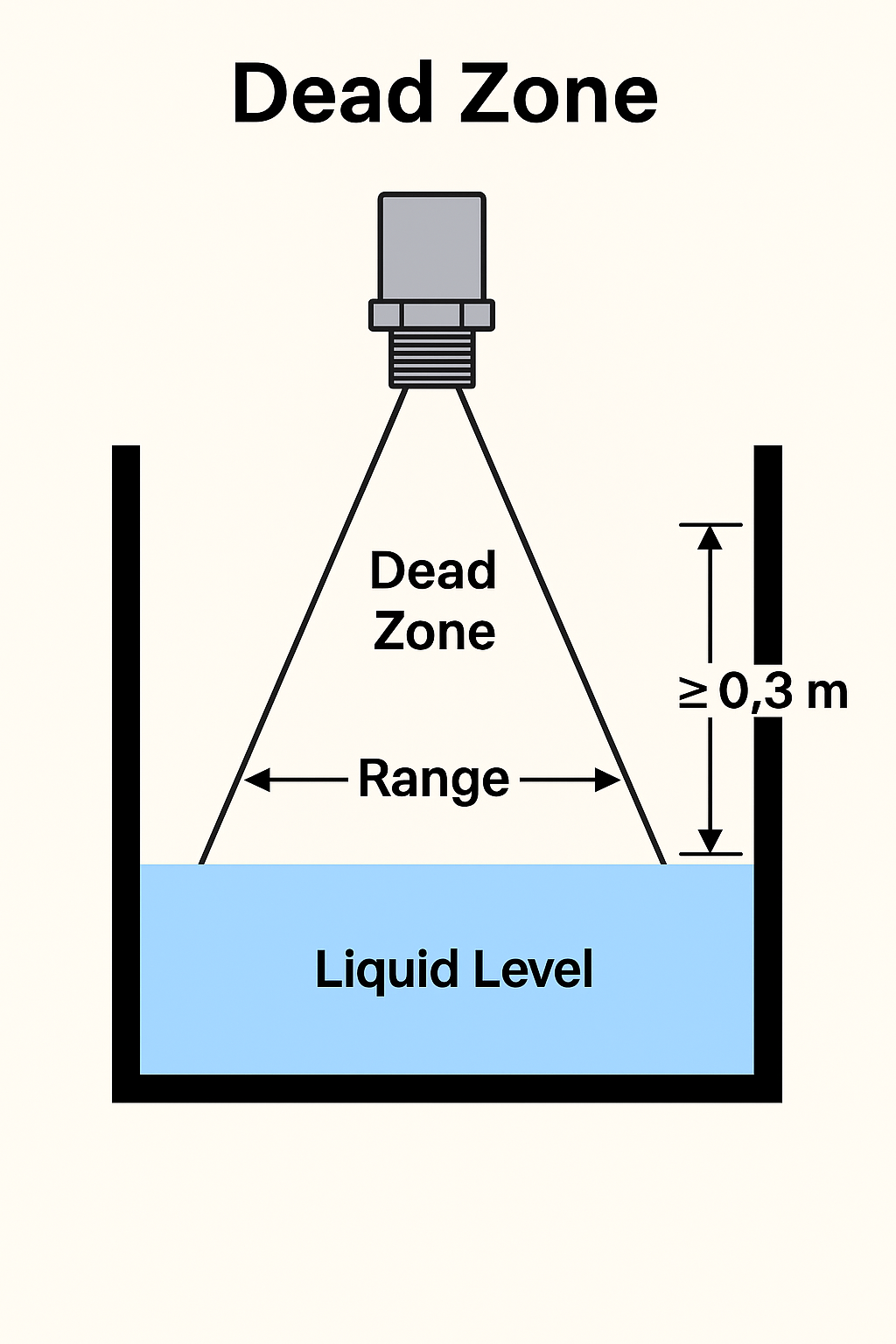
3.3 Blind Zone Verification
Confirm that the maximum liquid level maintains a safe distance from the probe, typically greater than the blind zone lower limit (e.g., 0.3 meters). This prevents measurement errors due to entering the dead zone.
4. Environmental Disturbance Simulation Tests
4.1 Foam and Steam Interference Testing
Spray clean water onto the liquid surface to simulate foam and observe if the level reading fluctuates. If signal scattering causes large fluctuations, consider installing a stilling tube or lowering sensor sensitivity.
Release a small amount of steam inside the container to verify if stable output is maintained. If significant interference occurs, reposition the probe or enhance ventilation.
4.2 Vibration and Agitation Testing
Operate an agitator or simulate vibration and observe data fluctuations. Fluctuations should remain within an acceptable range (e.g., ±5 mm). If fluctuations exceed limits, consider using a model with stronger anti-interference capability or reinforce the mounting bracket.
5. Signal Stability and Communication Interface Testing
5.1 Continuous Operation Testing
Operate the level sensor continuously for 24 hours while recording output data trends. Under normal conditions, the output curve should remain smooth without abrupt jumps.
5.2 Communication Verification
For 4–20 mA or RS485 communication output, use a multimeter or upper computer software to verify signal stability and ensure data synchronization with the PLC system.
6. Troubleshooting and Maintenance Recommendations
| Common Issues | Solutions |
|---|---|
| Display value jumps or fluctuates abnormally | Clean the probe surface; check if the shielding layer of the cable is damaged |
| Liquid level entering the blind zone | Adjust the installation height or add an extension tube to ensure the liquid stays below the blind zone |
| Signal affected by electromagnetic interference | Re-route wiring to avoid parallel routing with VFDs or high-power devices; improve grounding measures |
| Data drift due to high temperatures | Use a split-type installation, relocating the electronic unit to a shaded area; ensure the probe withstands ≥80°C |
Conclusion
By following the above testing procedures, you can comprehensively verify the measurement accuracy, anti-interference capability, and long-term stability of food-grade ultrasonic level sensors. This ensures compliance with food production hygiene and safety standards.