Because of its simple structure, reliable performance, intuitive reading, small and constant pressure loss, approximate linear scale, wide measurement range, convenient maintenance, and low price, the float flowmeter is widely used in flow measurement and control occasions such as liquids and gases.
In the application of various types of flow meters in China, it has a large quantity and a wide range. Based on the design principle, during the measurement process, the float flowmeter always keeps the pressure drop before and after the float unchanged and changes the flow by changing the flow area, so it is called a constant pressure drop flowmeter or a variable area flowmeter.
The tapered tube is made of different materials, divided into two types: glass tube float flowmeter and metal tube float flowmeter. Glass tube float flowmeters are mostly used in petrochemical, light industry, food, environmental protection, and other industries to measure the flow of non-pulsating fluids such as transparent liquids at room temperature and pressure or various gases.

It has the characteristics of simple structure, intuitive on-site measurement readings, and easy maintenance. Due to the limitation of its structure, the flowmeter can only indicate on-site, and cannot transmit flow signals remotely.
Because of the strength of the glass tube, it cannot be used to measure high temperature, high pressure, and opaque fluids. The metal tube float flowmeter, because the cone tube is made of metal, makes up for the defects of the glass tube float flowmeter.
The metal tube float flowmeter can withstand high temperature and pressure and can measure opaque and corrosive fluids. It can not only indicate the flow rate on the spot, but also transmit the flow rate signal remotely, which can realize multiple functions such as recording, totalizing, and automatic control.

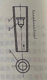
1. Working principle
The working principle of the float flowmeter is composed of a vertical tapered tube that expands upwards and a float that can move up and down freely in the tapered tube, as shown in Figures 8-1.
When the fluid flows through the tapered tube from bottom to top, it is throttled by the float, and differential pressure is generated between the upstream and downstream of the float. When the rising force of the float is greater than the weight of the float in the fluid, the float rises.
As the float rises, the annulus area between its maximum outer diameter and the tapered tube gradually increases, so that the rising force acting on the float gradually decreases until the rising force equals the weight of the float in the fluid, that is, Achieving a balance of power. At this time, the float is stable at a certain height, and the height of this position represents the flow value of the float flowmeter. Figure 8-1 Working principle
Structure type of float flowmeter The basic structure of the float flowmeter is composed of a tapered tube and a float, which are two main components, and other components include the base, bushing, and sealing packing. Float flow meters can be divided into two types: glass tube float flow meters and metal tube float flow meters.
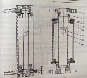
1. Junction structure type of glass tube float flowmeter (1) Structure type As shown in Figure 8-2, the glass tube float flowmeter is composed of a vascular tube, a float, and the upper and lower bases connected by the pipeline, the sealing base ring, and the upper and lower stops.
The tapered tube generally selects transparent materials with higher strength, such as high borosilicate glass, quartz glass, etc. The taper of the tapered tube is determined by the flow rate and the flow range.

The greater the taper of the tube, the greater the measured flow rate. Generally, the surface of the cone tube is engraved with the percentage of the flow rate or directly engraved with the flow value of the water or air.
There are many kinds of float shapes, which can be selected according to factors such as the flow measurement range, the stability of the float work, the application range of the flow coefficient to the viscosity of the medium, and the manufacturing process. The material of the float should be selected according to the chemical properties of the measured medium, generally made of hard aluminum, stainless steel, hard rubber, bakelite, and plastic.

The flowmeter and the pipeline are connected by flange connection, thread connection, and hose connection. Generally, the structure of a glass tube float flowmeter is divided into three types: the one with a smaller nominal diameter, which is larger than 4mm, 6mm, and 10mm, its structure is two separate square bases at both ends. The two bases are connected by a support plate, and the outside is covered with a plexiglass shield.
The glass tube is fixed on the base with a gland and an O-ring seal. A needle valve is installed on the base, and a tapered nozzle is installed at the back of the base for hose connection. Its flow adjustment method is self-adjusted with needle valve and without needle valve.
The second type has a diameter of 15mm, 25mm, and 40mm, and its structural feature is that when the flowmeter is installed on the pipeline and the glass tube needs to be replaced or cleaned, there is no need to remove the flowmeter from the pipeline, just loosen the gland.
The tube can be taken out horizontally. There is also a fixed structure, which is generally suitable for diameters of 50mm, 80mm, and 100mm. Its structure is basically the same as the first type.
Because the float in the large-diameter flowmeter is heavier, it prevents the glass tube from being damaged by the sudden drop of the float. Install a guide rod in the middle of the float. These two types of flowmeters are generally flanged or threaded.

(2) Model specifications
The glass tube float flowmeter can be divided into the following types. The ordinary type (LZB type) measuring medium is liquid and gas. Nominal diameter from LZB-2-LZB-15. The part of the material that the flowmeter is in contact with the measured medium, such as the base material, is mainly made of brass, cast iron lining, and cast iron inner coating.
The material of the stop is mainly polytetrafluoroethylene, and the large diameter is internally coated with cast iron. The material of the float mainly adopts stainless steel, and the small diameter adopts an agate ball. The sealing packing of the flowmeter is acid and alkali-resistant rubber.
The glass material of the tapered tube is high borosilicate glass. Corrosion-resistant type (LZB type and LZJ type) measuring medium is liquid and gas, the nominal diameter is from LZB-15F-LZB-100F, LZJ-15F-LZJ-50F. The part of the flow meter in contact with the measured medium is made of high borosilicate glass, and the rest are made of PTFE (Neecun) and F46 diaphragm. LZB-S type is dedicated to water meter calibration devices and can also be used on other occasions. LZT-S type (plastic tube) is a plastic tube flowmeter, the tube body material is AS, and the joint is ABS.

2. The structure of the metal tube float flowmeter
(1) Structure type The metal tube float flowmeter is composed of a sensor part and a conversion display part. The sensor is divided into several forms such as basic type, insulation jacket type, and corrosion-resistant type. The basic sensor, that is, the parts in contact with the measured fluid is made of stainless steel Cr18Ni9Ti, so it can be applied to a higher pressure range and a wider temperature range and has good corrosion resistance.
The thermal insulation jacketed sensor is a double-layer shell with a jacket space in the middle, during which it can be heated by steam or hot water to prevent significant changes in the density and viscosity of the fluid being tested and solidification in the middle of the pipeline.
It can also be clamped. The sleeve is drawn into vacuum heat insulation to prevent the measured low-temperature fluid from absorbing heat from the outside, avoiding the malfunction of the float or the decrease of measurement accuracy. Corrosion-resistant sensors, that is, the parts in contact with the measured fluid are protected by corrosion-resistant materials,
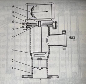
It is mostly used for flow measurement of strongly corrosive fluids such as strong acid and strong salt. The conversion display part can be divided into indicating type metal tube float flowmeter, gas remote transmission type metal tube float flowmeter, and electric remote transmission type metal tube float flowmeter. Indicating metal tube float flowmeter is mainly composed of two parts: measurement and indication. The two parts are coupled by magnetic steel to transmit the displacement of the float.
The measuring part is composed of a float, cone tube, guide rod, shell, and so on. The magnetic steel is located on the top of the guide rod, and there is a non-magnetic isolation tube outside. The guide ring and the isolation tube are used to limit the displacement of the guide rod and always keep the float and the tapered tube on the same centerline.
The indicating part is that the displacement of the float is coupled by the double-sided magnetic steel sealed in the magnetic steel and the indicating part, and the displacement of the float can indicate the flow value on the flow dial. The converter of the electric remote transmission metal tube float flowmeter is divided into a flow converter and an angular displacement converter. The flow converter is mainly composed of a pointer mechanism, a damping component, and a four-bar linkage mechanism.
It receives the displacement signal of the float in the sensor through magnetic coupling and displays the flow value on the flow dial by the pointer. The angular displacement converter is mainly composed of a magnetic balancer and an electrical processing unit. It receives the corner signal through a four-bar linkage and connects.
The corner signal is converted into 4mA -20mA. DC standard current signal output. Its working principle is that the displacement of the float causes the balance bar of the balance mechanism to shift through the coupling between the magnetic steels. After the transmission of the first set of four-link mechanisms, the pointer indicates the flow rate on the flow scale and has a compensation nonlinearity function.
Then through the transmission of the second set of four-bar linkage mechanisms, the rotor in the magnetic balancer is rotated. As the rotor rotates, the magnetic balance state changes. After detection and amplification, the output is 4mA ~ 20mA. DC standard current signal output and electric.
The unit combination instrument is matched to realize the flow indication and control. These signals can also be sent to the computer, and the instantaneous flow rate and cumulative flow rate can be displayed after processing.

The electric remote transmission metal tube rotor flowmeter includes the ordinary type and explosion-proof type. The explosion-proof type is suitable for the measurement of liquids and gases containing explosive mixtures and is suitable for use in environments containing explosive mixtures.
The structure of the gas remote transmission type metal tube float flowmeter is similar to that of the electrical remote transmission type metal tube float flowmeter, except that the remote transmission signal does not use an electrical signal but uses a 20-10kPa air pressure signal. Since the output is a standard pressure signal, it is suitable for explosive process flow.
At present, the gas remote transmission type metal tube float flowmeter is rarely produced by manufacturers.
(2) Model specifications The metal tube float flowmeter is divided into two major series: LZZH, LZDH, and LZZ, LZD. The LZZH and LZDH series is composed of a flowmeter tube body, standard orifice plate, conical float, and magnetic converter. The LZD series consists of a flow meter tube body, a standard float, a vascular tube, and a magnetic converter.

Classification of floating flowmeter structure type
(1) According to the classification of cone tube material, it can be divided into glass tube float flowmeter and metal cone tube float flowmeter.
(2) According to the classification of the output signal, it can be divided into two categories: field indication type and remote transmission type. The remote transmission type can be divided into electric remote transmission type and air remote transmission type.
(3) According to the classification of the tested fluid, it can be divided into float flowmeters for liquid, gas, and steam.
(4) According to the connection with the pipeline, it can be classified into hose connection, thread connection, and flange connection.
(5) According to the classification of flow meters, it can be divided into ordinary type, explosion-proof type, jacket insulation type, corrosion-resistant type, and so on.
(6) Float flow meters can be classified into full flow type and split flow type according to the amount of measured fluid passing through the flow meter and can be divided into the traditional type and intelligent type float flow meters.