1. General Concept of DCS System
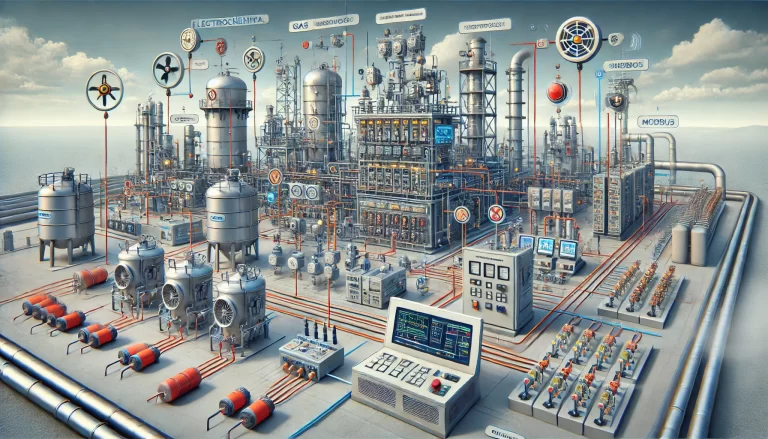
A Distributed Control System (DCS) is a computer-based control system used for industrial process automation. It combines distributed control units (at the field level) with a centralized operation and monitoring system (at the upper level) to achieve real-time measurement, control, alarm handling, trend analysis, and management of production processes. DCS systems are widely used in industries such as:
Chemical and Petrochemical
Power Generation and Metallurgy
Pharmaceuticals and Pulp & Paper
Water Treatment and other Process Industries
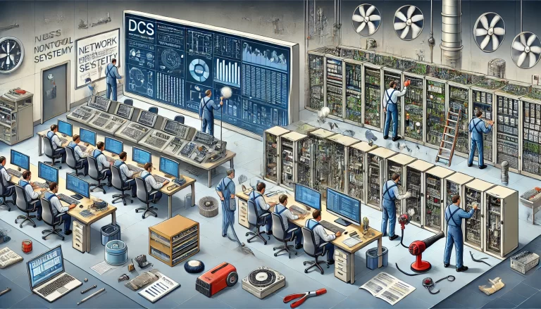
2. General Layout of the DCS System
A DCS system typically adopts a layered, distributed architecture, generally consisting of the following four levels:
| Level | Name | Main Equipment | Function |
|---|---|---|---|
| Level 1 | Field Level | Field Instruments, Actuators, Transmitters | Responsible for signal measurement and actuation (collecting data and controlling objects). |
| Level 2 | Control Level | Controllers, I/O Modules | Real-time signal collection, control algorithm execution (PID, logic, sequence control). |
| Level 3 | Operation Level | Operator Stations (HMI), Engineering Stations | Process monitoring, control, alarming, configuration, and historical trend analysis. |
| Level 4 | Management Level | Data Servers, MES Interface, Database | Production data management, report generation, communication with upper-level systems (ERP, MES). |
3. Detailed Explanation of Each Part of the DCS System
3.1 Field Level
Main Equipment:
Sensors and Transmitters (for pressure, temperature, flow, level, etc.)
Actuators (electric valves, control valves, variable frequency drives, motors)
Function:
Convert physical quantities (such as pressure and temperature) into standard signals (4-20mA, 0-10V, digital signals).
Receive control commands from the system and execute corresponding actions.
Communication:
Communicates with I/O modules via field buses (e.g., Foundation Fieldbus, Profibus, HART, Modbus).
3.2 Control Level
Core Equipment:
Control Station: The “brain” of the system, executing control algorithms.
I/O Modules: Responsible for signal acquisition and output, including analog (AI, AO) and digital (DI, DO) inputs and outputs.
Function:
Receives field-level signals via I/O modules.
Executes control strategies such as PID, logical control, and interlock protection.
Outputs control results to actuators.
Communicates with upper-level systems to upload data and alarm statuses.
Features:
Distributed deployment: Each control station operates independently, with redundancy.
Dual-controller hot backup (primary/secondary) to improve reliability.
3.3 Operation Level
Main Equipment:
Operator Stations (OCS or HMI): Used for real-time display of process flow.
Engineering Stations (ES): Used for configuration of control strategies, graphics, and parameters.
Alarm and Trend Servers: Used for alarm handling and historical trend analysis.
Function:
Real-time display of process flow diagrams.
Monitors production parameters, alarms, and trends.
Engineering Stations for configuration (control strategy, graphical screens, parameters).
Operator Stations for operational control (start/stop, adjustments, alarm acknowledgment).
Communication:
Connected to the Control Level through a Control Network (typically industrial Ethernet or dedicated industrial buses).
Operator Stations and Engineering Stations are connected via a Plant LAN.
3.4 Management Level
Main Equipment:
Historical Data Servers (HIS)
Report and Analysis Servers
MES/ERP Interface Servers
Function:
Stores and analyzes historical data.
Generates production reports and trend analysis.
Provides production data to upper-level management systems (ERP, MES).
Supports system integration through interfaces such as OPC, Modbus TCP/IP, and database connections.
4. Typical DCS Network Architecture (Text-Based Description)
┌─────────────────────────────────────────────┐
│ Management Level │
│ Data Servers / MES / Report Analysis │
└──────────────────────┬────────────────────┘
│ Ethernet
┌──────────────────────┴────────────────────┐
│ Operation Level │
│ Engineering Stations, Operator Stations, │
│ Historical Servers, etc. │
└──────────────────────┬────────────────────┘
│ Control Network (Industrial Ethernet)
┌──────────────────────┴────────────────────┐
│ Control Level │
│ Controllers / I/O Cabinets (with CPU and │
│ I/O Modules) │
└──────────────────────┬────────────────────┘
│ Field Bus
┌──────────────────────┴────────────────────┐
│ Field Level │
│ Sensors, Transmitters, Valves, Actuators │
└────────────────────────────────────────────┘
5. Key Features and Advantages of DCS
| Feature | Explanation |
|---|---|
| Distributed Control, Centralized Management | Control tasks are delegated to field controllers, while monitoring is centralized in the upper system. |
| High Reliability | Redundant controllers, communication, and I/O modules ensure system reliability. |
| Scalability | Modular design supports system expansion and network interconnection. |
| Powerful Data Management | Real-time and historical data storage, trend analysis, and alarm management. |
| User-Friendly HMI | Graphical interfaces that make operations and maintenance intuitive and easy. |
6. Conclusion: Understanding DCS
In summary, a DCS system is analogous to a “neural network” in industrial processes:
Sensors and actuators act as the “nerve endings.”
Control stations are the “brain cortex.”
The Operation Level is the “central system.”
The Management Level serves as the “thought and decision-making layer.”
The entire system works synergistically to ensure the safe, stable, efficient, and visual control of industrial processes.