Introduction
Orifice plate flowmeter is a standard orifice plate and multi-reference differential pressure transmitter (or differential pressure transmitter, temperature transmitter and pressure transmitter) to form a high range ratio differential pressure flow device, can measure the flow of gas, steam, liquid and natural gas.
Application
Widely used in petroleum, chemical, metallurgy, electric power, heating, water supply and other fields of process control and measurement.
Orifice flowmeter is widely used in coal, chemical industry, transportation, construction, light textile, food, medicine, agriculture, environmental protection and people’s daily life and other areas of the national economy, is the development of industrial and agricultural production, energy saving, improve product quality, improve economic efficiency and management level of an important tool in the national economy occupies an important position.
In process automation instruments and devices, flow meters have two main functions: as a detection instrument for process automation control systems and as a total meter for measuring material quantities.
Calibration testing
The flowmeter has a wide range of applications, all single-phase flow rates can be measured, and part of the mixed-phase flow can also use the product. Accurate measurement is not possible because of two-phase flow, and there is even a risk of water hammer and damage to the fittings.
If the annular orifice plate is used, condensate can flow away from the edge of the annular orifice plate and the minimum flow surface is a circle close to the inner wall of the tube, while the minimum flow surface of the standard orifice plate is a concentric circle in the center of the tube.
Impurities in the fluid flow rate are low, and are generally close to the edge of the tube wall flow, throttling device new varieties continue to emerge and promote the application, with the throttling device supporting the differential pressure transmitter and display instrumentation in the performance and quality of rapid development.
The inlet edge of the orifice flowmeter, which should be sharp and right-angled, becomes flared, changing the outflow coefficient and producing a large error that has to be replaced. As you can see, this product is the best choice for measuring the flow of high-temperature fluids.
Design Style
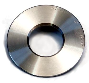
Fluid flow through the throttling device in the pipeline, in the throttling member near the cause of local contraction, the flow rate increases, in the upper and lower sides of the static pressure difference.
Orifice plate flowmeter throttling device structure is simple, and solid, stable and reliable performance, long service life, low price, is commonly used in industry to measure the flow of instruments, the whole process using international standards, and after strict calibration test.
Orifice flowmeter so that the flow rate increases, the static pressure is low, so the pressure drop before and after the throttle is generated, that is, the pressure difference, the greater the flow of the medium, the greater the pressure difference generated before and after the throttle, so the orifice flowmeter can measure the size of the fluid flow by measuring the pressure difference.
This measurement method is based on the law of energy conservation and the law of flow continuity.
Orifice plate flowmeter can measure the flow of various fluids in the pipeline, can measure the medium of liquid, gas, steam, is widely used in petroleum, chemical, metallurgy, light industry, coal mining and other industrial sectors.
Orifice flowmeter before and after the generation of a static pressure difference, the pressure difference and the flow of a certain function of the relationship, the greater the flow, the greater the pressure difference, the differential pressure signal sent to the differential pressure transmitter, converted into 4-20ma.DC analog signal output, far transfer to the flow accumulation meter, to achieve the measurement of fluid flow. Mass flow meter, the use of intelligent differential pressure transmitter, the temperature/pressure of the working conditions after automatic compensation, to achieve the measurement of fluid mass flow, the
Orifice plate flowmeter to send hot air, hot air furnace is generally closer to the blast furnace, and more elbows.
In the past, the use of standard orifice plate, because the straight section is not long enough and error. This meter because of the pressure equalization ring and multiple pressure taking port, need a 2D long straight pipe section can be.
After installation in the hot blast furnace air supply pipe, the application is very satisfactory, there have been more than thirty hot blast furnaces installed on the ring orifice plate flowmeter, operation for more than 3 years without failure.
Range of application
- Nominal diameter: 15 mm ≤ DN ≤ 1200mm orifice plate steam flowmeter
- Nominal pressure: PN≤40MPa
- Operating temperature: -50 ℃ ≤ t ≤ 550 ℃
- Range ratio: 1:10, 1:15
- Accuracy: 0.5 grade, 1 grade
Selection of models
- Piping conditions.
(1) The straight section of pipe before and after the throttle member must be straight and must not have a bend visible to the naked eye.
(2) The straight section of pipe used to install the throttle should be smooth, such as not smooth, the flow coefficient should be multiplied by the roughness correction factor.
(3) in order to ensure that the flow of fluid in the throttle before 1D forms a fully developed turbulent velocity distribution, and make this distribution into a uniform axisymmetric shape, so 1) the straight pipe section must be round, and the throttle before 2D range, its roundness requirements are very strict, and there are certain roundness indicators. Specific measurement methods: (A) before the throttle OD, D / 2, D, 2D 4 vertical pipe cross-section, with a large to equal angular distance of at least 4 pipe diameter single measurement, take the average value D. Any single measurement of internal diameter and the difference between the average value shall not exceed ± 0. 3% (B) after the throttle, in OD and 2D position with the above method, measured 8 single measurements of internal diameter, any single measurement, and D comparison, the maximum deviation shall not exceed ± 2%. (2) before and after the throttle requires a sufficiently long straight section of pipe, which is sufficiently long and the throttle before the form of local resistance parts and diameter ratio β, see Table 1 (β = d/D, d for the orifice diameter, D for the inner diameter of the pipe).
(4) the upstream side of the throttle member of the first resistance and the second resistance between the length of the straight pipe section can be in accordance with the form of the second resistance and β = 0. 7 (regardless of the actual β value is how much) to take the value listed in Table 1 1/2
(5) the upstream side of the throttle for the open space or diameter ≥ 2D large container, then the open space or large container and the throttle between the straight pipe length shall not be less than 30D (15D) if the throttle and open space or large container between other local resistance parts, in addition to the throttle and local resistance parts with a minimum length of the straight pipe section 1 on the attached table 1, from the open space to the throttle between the straight pipe section The total length of the straight pipe section from the open space to the throttle must not be less than 30D (15D).
Minimum length of straight pipe section on the upstream and downstream side of the throttle
The localized form of the upstream side of the throttle and minimum length of straight pipe section L
Note: 1. The above table is only for standard throttling devices, for special throttling devices can be referred to,
- The number of columns is a multiple of the inner diameter D of the tube.
- The above table outside the brackets for the “additional relative limit error of zero” value, the number in brackets for the “additional relative limit error of ± 0.5%” of the value. That is, the length of a straight pipe section using the value in brackets, the flow measurement limit relative error τQ/Q. Should be added arithmetically by 0.5%, that is, (τQ/Q + 0.5)%
4、If the actual length of the straight pipe section is greater than the value in brackets and less than the value outside brackets, it should be handled according to the “additional limit relative error of 0.5%”.
(1) DC parts installed in the pipe, its front surface must be perpendicular to the axis of the pipe, and the maximum perpendicularity allowed shall not exceed ± 1 °.
(2) After the throttle is installed in the pipe, its opening must be concentric with the pipe, and its maximum permissible non-centricity ε must not exceed the result calculated by the following formula: ε ≤ 0.015D (1/β-1).
(3) All gaskets must not be made of too thick material, preferably not more than 0.5mm, and the gaskets must not protrude from the pipe wall or they may cause a large measurement error.
(4) Any valve used to adjust the flow rate should be installed outside the minimum length of the pipe section after the throttle
(5) The installation of the throttling device in the process pipeline must be carried out after the pipeline cleaning and purging.
(6) in the horizontal or inclined pipeline installation of the throttling device to take the pressure way.
(1) When the fluid to be measured is liquid, in order to prevent air bubbles from entering the processing pipeline into the teeth, the pressure taking buckle should be in the position of ≤ 45° below the center line of the processing pipeline, plus or minus taking αα α1
Advantages and disadvantages
Advantages
1. the standard throttle is all-purpose and approved by the International Standards Organization, can be put into use without real-flow calibration, and is unique among flow sensors.
2. The structure is easy to copy, simple, solid, stable, and reliable performance, and low price.
3. A wide range of applications, including all single-phase fluids (liquid, gas, steam), part of the mixed-phase flow, general production process pipe diameter, and working conditions (temperature, pressure) can be measured.
4. Detection parts and differential pressure display instrumentation can be separated from different manufacturers to produce, to facilitate specialized scale production.
Disadvantages
1. The measurement of repeatability, accuracy in the flow sensor is a medium level, due to the complex impact of many factors, accuracy is difficult to improve.
2. The range is narrow, due to the flow coefficient and Reynolds number, the general range of only 3:1 to 4:1.
3. There is a long length of straight pipe section requirements, generally difficult to meet. Especially for larger pipe diameter, the problem is more prominent.
4. Large pressure loss.
5. Orifice plate in the hole sharp angle line to ensure accuracy, so the sensor is sensitive to corrosion, wear, scaling, dirt, long-term use of precision is difficult to ensure that the need to remove the strong inspection once a year;.
6. The use of flange connection, easy to produce run, bubble, drip, leakage problems, greatly increasing the maintenance workload.