Orifice flow meters dominate the industrial steam flow measurement field due to their simple structure, high reliability, and wide applicability. However, the high temperature and phase-change characteristics of steam present significant challenges in the stable transmission of differential pressure signals. As a key component in the pressure pipe system, the proper setup of the condensate pot directly influences both the accuracy and long-term stability of flow measurements. This article delves into the working principle of the condensate pot, analyzing its setup specifications based on GB/T 2624, ISO 5167, and practical engineering cases, with a particular focus on the differences between saturated steam and superheated steam.
1. The Working Principle of Orifice Flow Meters for Steam Measurement and the Emergence of Condensate Pots
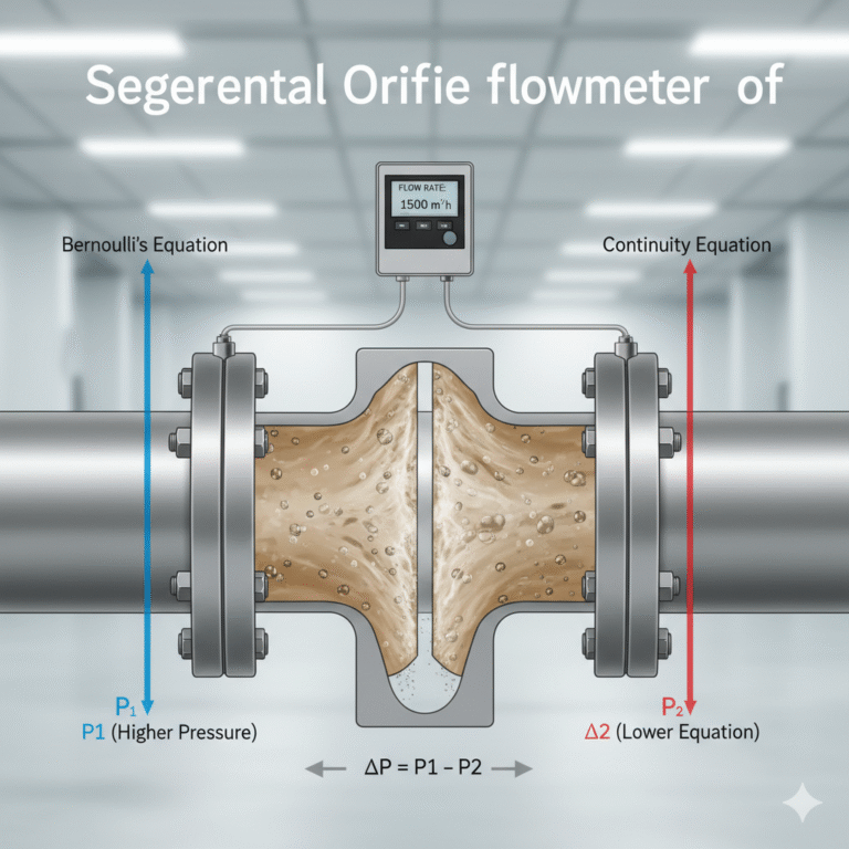
Orifice flow meters operate on the principle of differential pressure measurement. As fluid flows through the orifice plate, a differential pressure is created, which is proportional to the square root of the flow rate. For steam, typically, pressure is tapped through annular or flange connections, and the pressure signals are transmitted to a differential pressure transmitter via impulse lines. However, steam has an extremely high latent heat of vaporization and temperature (saturated steam ranges from 100°C to 250°C, while superheated steam can exceed 400°C). If high-temperature steam directly enters the impulse line and transmitter, it can lead to:
Damage or drift in the transmitter’s sensitive elements due to overheating.
Two-phase flow in the impulse lines caused by uneven steam condensation, leading to erratic differential pressure signals.
Static pressure errors caused by uneven condensate levels on the positive and negative pressure sides.
To address these issues, it is common practice to install a condensate pot (also called a steam condensate pot) near the pressure tap, which forces the steam to condense into liquid water. This ensures reliable separation of the steam from the transmitter and provides stable static pressure transmission.
The condensate pot is not a simple container. It is a precision component integrating condensation, liquid storage, isolation, and pressure stabilization. The typical structure is a cylindrical container made of carbon steel or stainless steel, with a volume of 0.5 to 5 liters and a design pressure that meets or exceeds the pipe design pressure. The condensate pot is equipped with an exhaust/drain valve at the top, impulse line connection, and a drainage valve at the bottom.
2. General Setup Guidelines for Condensate Pots
Regardless of whether dealing with saturated steam or superheated steam, the following condensate pot setup principles must be strictly adhered to. Any deviation can lead to significant measurement errors or system failure:
1. Geometric Position and Orientation
Position Near the Pressure Tap: The condensate pot should be installed directly above or below the pressure tap valve (root valve). The proper setup involves vertical upward pressure tapping for steam, with the condensate pot positioned above the pressure tap, ideally as close to the root valve as possible (typically ≤500mm). This ensures no excessive condensation occurs in this section.
Exact Height Alignment: The centerlines of both the positive and negative pressure side condensate pots must be at the same horizontal level, with a height difference controlled within ±2mm. This is crucial for ensuring that the differential pressure transmitter outputs correctly when there is zero differential pressure.
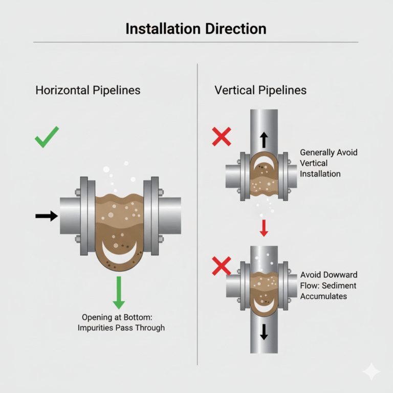
Vertical Installation: The condensate pot should be installed vertically to ensure the liquid level remains constant. The impulse line connection is usually located at the bottom center of the pot to ensure the impulse line is always filled with condensate water without air bubble buildup.
2. Impulse Line Slope and Routing
The impulse line from the condensate pot to the differential pressure transmitter should be inclined downwards (slope ≥1:10) with no “pocket” bends, allowing gases to naturally flow to the exhaust valve at the transmitter. The transmitter should be installed at the lowest point in the entire system and equipped with a three-valve assembly and a drain valve. Special attention should be given to ensure the transmitter is positioned at least 300mm lower than the lowest point of both condensate pots to maintain a fully liquid-filled condition in the condensate pots via gravity.
3. Water Filling and Venting of the Condensate Pot
Initial Setup: Upon initial operation or after maintenance, water must be manually filled into the condensate pot via the top screw plug or filling valve until fully filled, ensuring all air is expelled from the pot and impulse line. Steam should not be relied upon to fill the pot with condensate water during startup, as inconsistent condensation rates can cause significant fluctuations in the differential pressure signal, possibly even leading to transmitter overload.
Water Quality: The filling water must be clean and softened to prevent solid deposition.
4. Root Valve and Drainage Attachments
Each condensate pot should be accompanied by a root valve at the pressure tap, a drainage valve at the bottom of the pot, a drainage valve at the lowest point before the transmitter, and a three- or five-valve assembly. After filling, the screw plug on the top filling valve must be tightened to prevent steam leakage.
Engineering Warning
In a certain chemical plant, a superheated steam measurement system failed after not following equal-height installation for condensate pots. The transmitter was located above the condensate pot, resulting in reverse and fluctuating differential pressure signals. Inspection revealed that the condensate pot was empty, and high-temperature steam directly entered the transmitter, causing silicon oil carbonization. The issue was resolved after reinstalling the condensate pot as per specifications.
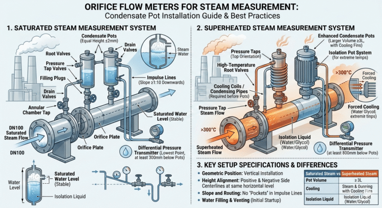
3. Saturated Steam Flow Measurement: Condensate Pot Setup
Saturated steam, which exists in a liquid-vapor coexistence state, is highly susceptible to condensation when exposed to environmental cooling. The main challenge in measuring saturated steam flow is maintaining equal liquid levels in the two condensate pots and preventing steam from entering the impulse line, particularly in cold conditions.
1. Typical Setup Diagram for Saturated Steam Condensate Pots
(Insert illustration here)
2. Key Considerations for Saturated Steam
Condensate Level Stability: Saturated steam condenses rapidly, and the condensate level in the two pots may slightly differ due to uneven heat dissipation. To minimize this, increasing the condensate pot volume (diameter ≥100mm, height ≥250mm) can help stabilize the liquid level fluctuations.
Preventing Steam Penetration: If the condensate pot’s liquid level drops too low, steam can break through the water seal and enter the impulse line, causing flow measurement disruption. To address this, a low-liquid-level alarm should be installed.
Freeze Protection: In northern climates, if steam supply is intermittent, the water in the condensate pot may freeze. Solutions include using heated condensate pots, draining the pot when not in use, or adding antifreeze (such as glycol-water mixtures). Electrical heat tracing is the recommended solution for maintaining a temperature of 5–20°C.
3. Special Water Filling Procedure for Saturated Steam Systems
Water Filling Process: Upon initial startup, the condensate pot must be manually filled with water, and the root valve should be gradually opened once the pipe temperature approaches the steam temperature. The transmitter should be activated slowly to prevent water hammer caused by rapid condensation.
4. Superheated Steam Flow Measurement: Condensate Pot Setup
Superheated steam, which is dry, water-free, and has high temperature (typically >300°C), poses a different challenge. If the heat dissipation of the condensate pot is insufficient, the steam will not condense properly, and the liquid level cannot be maintained.
1. Core Issues in Superheated Steam Condensation
Vaporization of Condensate: If the condensate pot cannot adequately cool the steam below 100°C, it will cause boiling and secondary steam formation, making it impossible to maintain a stable liquid level.
Impulse Line High Temperature: The impulse line can experience temperature-related measurement drift due to uneven water column density caused by low environmental temperatures.
Density Compensation Complexity: The density of the condensate water at high temperatures must be corrected, as it differs significantly from standard water density.
2. Engineering Measures to Ensure Effective Condensate Water Storage
Enhanced Heat Dissipation: Install cooling coils or extended impulse lines to reduce the temperature of superheated steam entering the condensate pot to below 80°C. This ensures that the pot contains subcooled water.
Increased Pot Volume and Metal Quality: Use larger condensate pots (diameter ≥150mm), made from thermally conductive stainless steel with cooling fins on the outer surface to enhance heat dissipation.
Isolation Systems: For extreme high-temperature steam, a two-pot system, where the first condensate pot condenses steam into hot water, which is then used to heat the isolation liquid in a second pot, can be employed.
3. Special Installation Requirements for Superheated Steam Condensate Pots
Pressure Tap Direction: The pressure tap should be at the top of the pipeline, and the root valve should be high-temperature resistant.
Transmitter Installation Height: The transmitter should be at least 800mm below the condensate pot, allowing for a higher static pressure head.
Heat Tracing: Heat tracing should be minimal, just enough to prevent freezing in winter conditions.
5. Key Differences in Setup for Saturated vs. Superheated Steam Condensate Pots
| Comparison Item | Saturated Steam | Superheated Steam |
|---|---|---|
| Primary Goal | Maintain equal liquid columns, prevent steam penetration | Force cooling and prevent vaporization |
| Pot Volume | Standard (0.5–2L) | Larger or with cooling structures (≥3L) |
| Cooling Coils | Generally unnecessary | Required for cooling |
| Impulse Line Heat Tracing | Controlled to prevent freezing | Must not be heated excessively |
| Density Correction | Low risk of error | Requires correction due to high temperature |
| Water Filling Process | Direct filling after setup | Requires monitoring of cooling efficiency |
6. Standard Operating Procedure (SOP) for Condensate Pot Setup
Follow this 12-step procedure to avoid errors during setup:
Verify drawings and pipe installation directions.
Install condensate pot brackets above the pressure tap.
Install the root valve and condensate pot.
Lay impulse lines with a ≥1:10 slope.
Install the transmitter and three-valve assembly.
Perform system pressure testing.
Fill the condensate pot with clean deionized water.
Calibrate the zero point.
Gradually preheat the system for startup.
Check balance valves for proper operation.
Record initial parameters.
Conduct regular inspections and drainage.
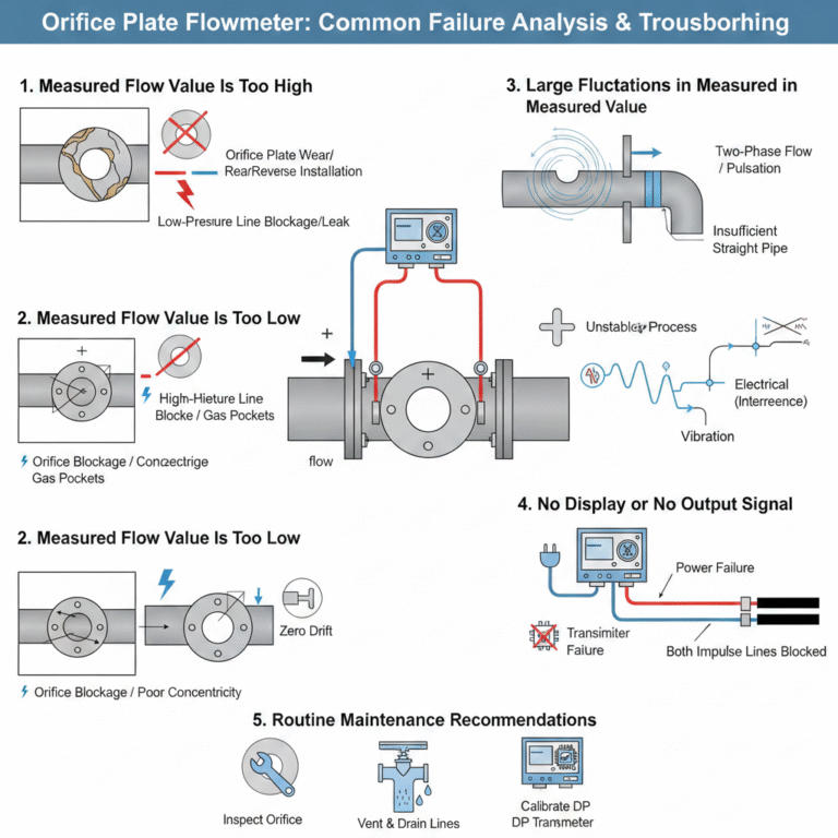
7. Common Failure Modes and Solutions
Issue 1: Differential pressure signals drift in one direction. Likely caused by a low liquid level in the condensate pot. Solution: Refill the condensate pot and check the temperature.
Issue 2: Severe pressure fluctuations. Likely caused by vaporization inside the condensate pot. Solution: Add more cooling capacity or replace with a water-cooled condensate pot.
Issue 3: Pot freezing in winter. Solution: Drain the pot during downtime or use antifreeze.
8. Standards on Condensate Pot Setup
GB/T 2624.1-2006: Recommends using a balanced condensate pot for steam measurement.
ISO 2186:2007: Describes condensate pot setup principles.
SH/T 3104-2013: Emphasizes condensate pot installation for differential pressure transmitters.
Conclusion: The Importance of Proper Condensate Pot Setup for Steam Flow Measurement
The condensate pot is an essential component in steam flow measurement systems. Despite its simple appearance, it plays a crucial role in phase separation, pressure transmission, and temperature control. Proper setup, as outlined in this article, is key to ensuring the accuracy and reliability of steam flow measurements.