Question: Should a differential pressure level transmitter be drained while in operation?
Answer: Generally, it is not recommended to drain a differential pressure level transmitter while it is in operation. However, if drainage is necessary, follow the steps below:
Disable Automatic Water Level Control: First, disengage the automatic water level control and switch to manual operation.
Open the Equalizing Valve: After switching to manual, open the equalizing valve to balance the pressure across both sides of the transmitter.
Proceed with Draining: Once the equalizing valve is open, initiate the drainage process by opening the drain valve.
Close the Drain Valve: After the drainage is complete, close the drain valve.
Check Transmitter Output: Following the closure of the drain valve, the transmitter’s differential output should show 100%.
Close the Equalizing Valve: After confirming the output, close the equalizing valve.
Return to Automatic Control: Once the transmitter’s output returns to normal, switch back to automatic water level control.
By following this sequence, the differential pressure transmitter can be drained safely without causing malfunction or error in its readings.
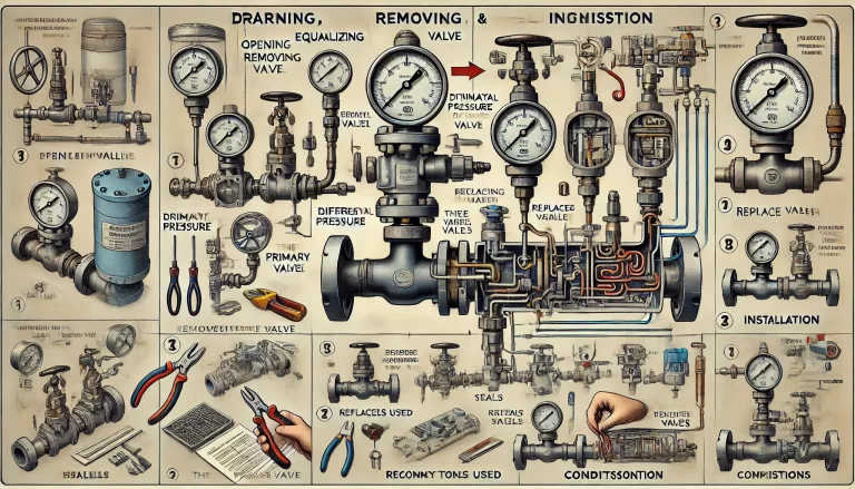
Part 1: Removal of the Transmitter
When removing a differential pressure transmitter, proper care must be taken to ensure that the device and its components are not damaged. Follow the steps below:
Disconnect the Transmitter Wiring: Carefully disconnect the transmitter wiring, making sure to label each connection for proper reinstallation. Wrap the signal wires with insulating tape to prevent any short circuits due to grounding.
Select Appropriate Tools: Use the correct tools to remove the transmitter, ensuring no damage occurs during the process.
Remove the Transmitter Along with the Three-Valve Manifold: Once disconnected, remove the transmitter along with the attached three-valve manifold. Be mindful to protect the instrument connections from dirt and damage after removal.
Replace Seals: If you plan to remove the three-valve manifold, the seals must be replaced. For instance, when disassembling a differential pressure transmitter with a diaphragm-sealed flange, the O-ring seals must be replaced.
Regular O-ring Replacement: O-rings should be replaced periodically according to the operating environment, as their lifespan can be affected by wear and tear.
Part 2: Installation of the Transmitter
To install a differential pressure transmitter, follow these guidelines:
Use the Correct Tools: Select the proper tools and follow standard procedures to install the transmitter.
Check the Flange and O-Ring: When connecting the transmitter with the flange, ensure that the Teflon O-ring is installed correctly. If a new O-ring is used, tighten the flange bolts again after installation to compensate for cold deformation.
Inspect Tube and Valve Connections: For connections using ferrule fittings, ensure that the ferrule has formed a prominent bulge at the front after compression, fully enclosing the ferrule. Check that the ferrule is securely fastened and properly sealed.
Reconnect Power and Signal Wires: Open the transmitter’s junction box and properly connect the power and signal wires. Be sure to seal the junction box tightly and avoid any potential for short circuits.
Close Valves: After installation, ensure that the primary valves, vent valves, and drain valves are all closed before proceeding.
Part 3: Commissioning the Transmitter
When putting the differential pressure transmitter back into service, proceed as follows:
Coordinate with Operators: Notify the process operators and ensure that the control loop is in manual mode, and the interlock loop is in bypass mode.
Verify Correct Installation: Confirm that the differential pressure transmitter has been installed correctly, ensuring that all connections and instruments are secure.
Check Valves: Make sure the primary valves, vent valves, and drain valves are closed, while the equalizing valve is open. Ensure the three-valve manifold is in the proper position.
Power Up the Transmitter: From the control room, close the supply switch to power up the transmitter.
Verify Zero Reading: Observe whether the transmitter displays a zero reading. If not, make the necessary adjustments.
Gradually Open the Primary Pressure Valve: Slowly open the primary pressure valve to introduce pressure to the system.
Adjust the Three-Valve Manifold: Open the high-pressure valve of the three-valve manifold and then close the equalizing valve.
Open the Low-Pressure Valve: After the equalizing valve is closed, open the low-pressure valve.
Check for Leaks: Inspect the transmitter, impulse lines, valves, and unions to ensure there are no leaks.
Verify Normal Operation: Confirm that the transmitter’s readings are stable and within normal ranges.
For Transmitters Requiring Sealing Fluid: If the differential pressure transmitter requires sealing fluid, make sure to fill the system correctly. Eliminate any air bubbles and adjust the transmitter’s zero reading before commissioning.
Following these detailed steps ensures the safe and correct removal, installation, and commissioning of differential pressure level transmitters, reducing the risk of operational issues.