A pressure transmitter is an instrument that converts pressure into a 20-100 kPa pneumatic signal or a 4-20 mA current signal. Pressure transmitters are categorized into pneumatic and electric types and are widely used in industries such as refining, chemical processing, metallurgy, and pharmaceuticals. On-site calibration of pressure transmitters is a common practice.
1. Tools and Instruments On-site calibration of pressure transmitters does not require disassembly or special tools. Common wrenches of 200mm or 250mm (8″ or 10″) and standard tools for instrument technicians are sufficient. The error limit of the calibration instrument should be between 1/3 to 1/10 of the error limit of the transmitter being calibrated.
| Name | Specifications & Model | Unit | Quantity | Remarks |
|---|---|---|---|---|
| Piston Pressure Gauge | YS-60 or YS-600 | Unit | 1 | Select based on the range of the instrument being calibrated |
| Digital Pressure Gauge | Unit | 1 | Select based on the range of the instrument being calibrated | |
| Precision Ammeter | 0~30 mA | Unit | 1 | |
| Rubber or Steel Tube | Meter | 1 | ||
| Electrical Wire | Meter | Several |
2. Wiring The wiring diagram for calibrating an electric pressure transmitter is shown in Figure 1-3.
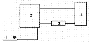
Figure 1-3: Wiring Diagram for Calibrating Electric Pressure Transmitters
- Piston pressure gauge; 2. Transmitter under calibration; 3. Precision ammeter; 4. 24VDC power supply
3. Operational Steps
Steps for calibrating an electric pressure transmitter:
- Basic Error Calibration
- Close the valve on the pressure line connected to the transmitter and disconnect the original pressure line fitting. Connect the piston pressure gauge, and wire the calibration circuit according to Figure 1-3.
- After checking and confirming the setup, power on the system.
- Select the pressure transmitter’s measurement range or output signal’s 0%, 25%, 50%, 75%, and 100% points as the standard values for calibration.
- Gradually increase the pressure signal using the piston pressure gauge and record the actual measured values at each point.
- Raise the output signal to 105% of the upper limit and hold for 2 minutes, then gradually reduce the output signal to the minimum value and record the actual measured values.
- Calculate the basic error using the following formulas:
Forward travel error (δz) = (Az – Ao) / 16 × 100%
Reverse travel error (δz) = (Af + Ao) / 16 × 100%Where:
- δz: Basic forward travel error, %
- δz: Basic reverse travel error, %
- Az: Measured output value during forward travel, mA
- Af: Measured output value during reverse travel, mA
- Ao: Nominal output signal value, mA
- 16: Difference between the upper and lower limits of the output signal, mA
The basic error of the electric pressure transmitter must not exceed the accuracy level specified by the transmitter.
- Backlash Error Calibration The backlash error is the absolute difference between the forward and reverse travel measured values at the same point. It is calculated as follows:AH = |AZ – AF|
Where:
- AH: Backlash error of the electric pressure transmitter, mA
- AZ: Measured output value during forward travel, mA
- AF: Measured output value during reverse travel, mA
The backlash error of the electric pressure transmitter must not exceed the allowed basic error limit.
- Filling in Calibration Records The calibration form for electric pressure transmitters typically includes the following:
- Unit
- Instrument name
- Model and specifications
- Accuracy level
- Measurement range
- Manufacturer
- Serial number
| Output Signal | Nominal Output Value (kPa) | Measured Output Value | Error (kPa) | Backlash Error (kPa) | % (kPa) |
|---|---|---|---|---|---|
| Forward | Reverse | Forward | Reverse | Forward | |
| 0 | |||||
| 25 | |||||
| 50 | |||||
| 75 | |||||
| 100 |
Also, include:
- Allowed basic error: Maximum basic error
- Allowed backlash error: Maximum backlash error
- Calibrated by: Reviewed by: Date (Year, Month, Day)