Differential pressure transmitters are categorized into pneumatic and electric types. They are widely used in industries such as refining, chemical processing, and metallurgy. These transmitters are often paired with throttling devices to measure flow, and sometimes are used to measure liquid levels or other parameters. Many differential pressure transmitters operate directly on-site, where most calibrations are also performed in the field.
1. Tools and Instruments On-site calibration of differential pressure transmitters generally does not require disassembling the transmitter. First, close the positive and negative pressure valves of the pressure tube, open the balance valve, and remove the plugs from the positive and negative pressure vent holes. The pressure signal can enter the transmitter from the positive pressure side through the calibration port, while the negative pressure side is open to the atmosphere. There are no special requirements for the calibration tools; common wrenches (150mm or 200mm) and standard tools for instrument technicians can be used. The standard instrument for calibration should have an error limit that is 1/3 or 1/10 of the error limit of the instrument being calibrated.
| Name | Specifications & Model | Unit | Quantity |
|---|---|---|---|
| Digital Pressure Gauge | Range depends on the instrument being calibrated | Unit | 1 |
| Precision Ammeter | 0~30mA | Unit | 1 |
| Air Source Pressure Regulator | Piece | 1 | |
| Pneumatic Regulator | Piece | 1 | |
| Air Source Tube Tee | Φ6 (Φ8) | Piece | 1 |
| Rubber or Steel Tube | Φ6 (Φ8) | Meter | |
| Electrical Wire | Meter | Several | |
| Calibration Port |
Note: Field conditions usually lack a gas supply, so a hand pump is often used instead of a pressure-reducing valve and pneumatic regulator.
2. Wiring The calibration wiring described in this document applies to instruments that are taken out of service. For on-site calibration without removing the instrument, you can connect the wiring based on actual conditions. For pneumatic instruments, an additional air source is not necessary, and for electric instruments, no extra power supply is needed. Figure 1-1 shows the calibration wiring diagram for electric differential pressure transmitters.
For high-pressure differential transmitters, the input signal can be provided by a piston pressure gauge. Field calibration typically uses the on-site power supply.
Figure 1-1: Calibration Wiring Diagram of Electric Differential Pressure Transmitters
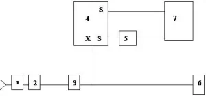
- Air source shut-off valve; 2. Pressure-reducing valve; 3. Pneumatic regulator; 4. Instrument being calibrated;
- Precision ammeter; 6. Digital pressure gauge; 7. Power supply; x – Input; s – Output
3. Operational Steps The calibration steps for electric differential pressure transmitters are as follows:
- Basic error calibration
- Close the positive and negative pressure valves of the pressure tube and open the balance valve.
- Follow Figure 1-1 to set up the calibration wiring.
- Remove the plugs from the positive and negative vent holes.
- Use air to clean out any remaining liquid from the positive and negative pressure chambers through the vent holes.
- After confirming the setup, connect the power supply.
- Apply the signal to the positive pressure side through the calibration port. Use the 0, 25%, 50%, 75%, and 100% output signal points of the transmitter for calibration.
- Gradually output the differential pressure signal and record the actual measured values at each point.
- Increase the output signal to 105% of the upper limit and hold for 1 minute, then gradually decrease the output signal to the minimum, recording the actual measured values at each point.
- Calculate the basic error using the following formulas:
Forward travel error (δz) = (Az – Ao) / 16 × 100% Reverse travel error (δz) = (Af + Ao) / 16 × 100%
Where:
- δz: Basic error of forward travel, %
- δz: Basic error of reverse travel, %
- Az: Measured output value during forward travel, mA
- Af: Measured output value during reverse travel, mA
- Ao: Nominal output signal value, mA
- 16: Difference between the upper and lower limits of the output signal, mA
The basic error of the electric differential pressure transmitter must not exceed the accuracy level specified by the transmitter.
- Backlash error calibration The backlash error is the absolute difference between the forward and reverse travel measured values at the same point. It can be calculated as follows:
- AH = |AZ – AF|
Where:
- AH: Backlash error of the electric differential pressure transmitter, mA
- AZ: Measured output signal value during forward travel, mA
- AF: Measured output signal value during reverse travel, mA
The backlash error of the electric differential pressure transmitter must not exceed the allowable error limit.
- Fill in the calibration records
- Calibration form:
- Unit
- Instrument name
- Model
- Accuracy level
- Measurement range
- Manufacturer
- Serial number
Output Signal Nominal Output Value / kPa Measured Output Value Error / kPa Backlash Error / kPa % / kPa Forward Reverse Forward Reverse Forward Reverse 0 25 50 75 100 Record the maximum basic error, allowed basic error, maximum backlash error, and allowed backlash error.
- Calibration personnel
- Auditor
- Date (Year, Month, Day)
- Calibration form: