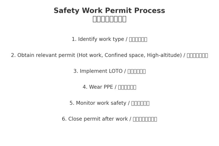
Before starting troubleshooting work, contact the production unit to understand the fault phenomenon and operating status by checking historical trends, valve openings, and communicating with operators. Initially determine whether the problem is caused by the instrument or the process. – For general measurement loops: Obtain process permission before starting work. – For control loop instruments: Confirm the loop is in manual mode and obtain process permission. – For interlocked instruments: Contact instrumentation management to disable the interlock and obtain the required work permits. – For checks before the primary isolation valve: Obtain maintenance permits, pipeline opening permits, and an energy isolation list, then implement lockout-tagout procedures. – Wear proper PPE: maintenance overalls, safety helmet, protective gloves, and anti-static safety shoes. – For work above 2 m: Obtain a high-altitude work permit and wear a safety harness. – For confined space work: Confirm process safety, obtain confined space work permits, and perform hazardous gas testing. – Prepare common maintenance tools and communication equipment (pipe wrench, spanners, screwdrivers, multimeter, oil catchers, cloth, HART475 communicator, etc.). For flammable gases/liquids, use explosion-proof tools. For toxic media, carry portable gas detectors and protective equipment.
2. On-site Inspection Steps
Check if the instrument’s indicator light shows any alarms. If yes, access the fault menu and record error codes. 2. Check valve opening to ensure the pipe is full. 3. Open the housing to inspect for water ingress or lightning arrester damage. Check power supply voltage with a multimeter. 4. Inspect wiring connections for tightness and absence of corrosion. 5. Verify proper grounding.
3. Common Fault Cases
3.1 Zero Drift
EN: Cause – U-tube sensor not fully filled, presence of liquid-gas mixture. Solution – Flush the pipeline, ensure full pipe, close downstream valve, observe zero point; if drift persists, perform zero adjustment. If occasional drift <3% of span occurs, adjust low-flow cut-off value accordingly (not exceeding 3%).
3.2 U-tube Noise and Vibration
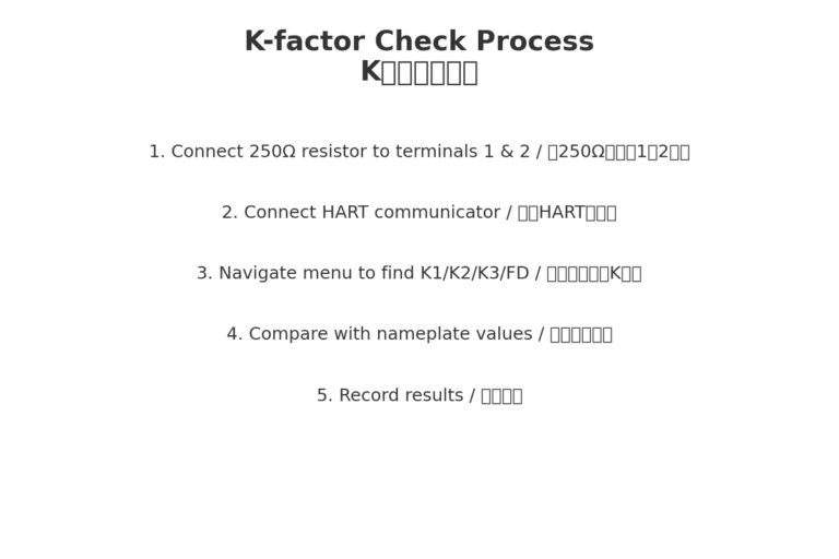
EN: Cause – U-tube not full or foreign matter inside, drive gain exceeds 20%. Solution – Flush pipeline and sensor, check K1/K2/K3/FD coefficients, clean and reinstall if necessary, ensure proper gasket and bolt installation, observe operation after commissioning.
By following the structured troubleshooting procedures outlined in this document—starting from proper preparation and safety measures, through systematic on-site inspection, and finally to targeted fault elimination—maintenance personnel can effectively resolve common mass flowmeter issues such as zero drift, noise, and vibration. Combining practical case studies with clear operational steps and visual aids ensures that even complex faults can be addressed quickly and safely, minimizing downtime and safeguarding measurement accuracy.