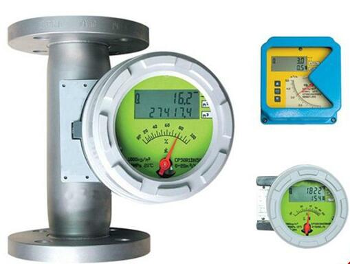
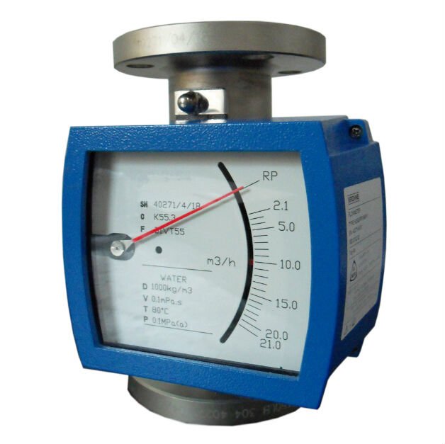
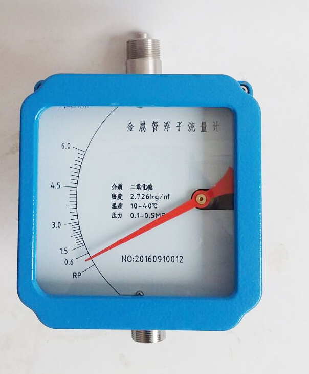
1. Key Maintenance Procedures for Rotameter Flow Meters
1.1 Pre-Maintenance Preparations
Process Coordination: Coordinate with the process department and obtain written approval. Verify that maintenance operations will not disrupt production or introduce safety risks.
Risk Assessment and Protection: Assess the corrosiveness, flammability, pressure, and temperature of the process medium. Wear appropriate PPE such as anti-corrosion gloves, goggles, and respirators. Use explosion-proof tools and implement a two-person safety protocol in explosive environments.
System Isolation: Ensure the flow meter is properly isolated from the process. Drain the pipeline thoroughly before disconnecting wiring or dismantling the instrument.
1.2 Maintenance Operations
Thorough Cleaning and Inspection: Use steam purging to clean the meter. Check the float’s movement within the tube for smoothness. Verify that the pointer moves synchronously with the float and that the zero and span settings are accurate. Inspect all mechanical connections and moving parts.
Reinstallation and Commissioning: Replace gaskets with new ones of proper specification. Clean all sealing surfaces before installation. After installation, reconnect wiring, recalibrate the zero point, and verify proper data display on the local or remote indicator.

2. Installation Considerations for Rotameter Flow Meters
2.1 Pre-Installation Checks
Device and Environment Inspection: Confirm the integrity of the flow meter—ensure the float, spring, and bearings are undamaged and free of debris. Verify that its specifications (e.g., range, material, pressure/temperature ratings) match the process conditions.
Installation Environment: Select a location within the instrument’s rated ambient temperature and humidity. Avoid proximity to high electromagnetic interference sources such as motors or transformers.
Pipeline Preparation:
Cleaning: Flush the pipeline to remove welding slag, rust, or sand that may cause float jamming or wear.
Inspection: Check for pipeline corrosion or leakage. Ensure vertical pipe runs are within allowable deviation.
2.2 Proper Installation Techniques
Flow Direction: Install according to the directional arrow on the meter body. In vertical installations, fluid must flow bottom-to-top. For horizontal installations, ensure the float is not affected by gravity.
Location Rules: Maintain a minimum of 5D upstream and 2D downstream straight pipe lengths to ensure laminar flow. Use a flow straightener if these lengths cannot be met.
Anti-Vibration Measures: If near vibrating equipment, install shock-absorbing brackets or rubber pads to minimize vibration impact.
Sealing and Electrical Connections:
Use gaskets suited to the fluid and pressure class. Tighten bolts diagonally and evenly.
For electronic models, ensure proper wire marking and grounding. Protect cables from heat, moisture, and mechanical damage.
2.3 Post-Installation Inspection and Testing
Visual Inspection: Ensure proper installation, verify all connections, and confirm no leakage or visible damage. Check the float movement and internal part assembly if possible.
Startup and Calibration:
Open valves slowly to fill the meter and monitor float behavior and display reading.
Calibrate the flow meter and adjust readings if necessary. Re-check operation after trial run to ensure stability.

3. Maintenance Case Studies
Case 1: Pointer Lag and Float Jamming
Issue: On-site pointer displayed abnormal lag; tapping the case had no effect.
Diagnosis: Disassembly revealed metallic debris on the float, likely due to magnetized iron rust from the process line.
Resolution: Cleaned the float and reassembled. Pointer resumed normal movement, and readings matched expected values.
Lesson: Install upstream filters and clean pipelines regularly to prevent magnetic material accumulation.
Case 2: Abnormal Output Signal
Issue: Analog display was normal, but current output was higher than expected (13 mA indicating 60% flow).
Diagnosis: Electrical insulation resistance test showed degraded cable insulation (<5 MΩ).
Resolution: Replaced signal cable. Output returned to normal and aligned with actual flow.
Lesson: Always include signal cable integrity in troubleshooting, especially in humid or corrosive environments.

Case 3: Gradual Drop in Flow Indication to Zero
Issue: Rotameter showed a gradual decrease in flow readings until zero.
Diagnosis: High-temperature ethylene glycol (180°C) was partially vaporizing due to pressure drop at the valve, forming bubbles that disrupted float movement.
Resolution: Installed air vent and scheduled periodic purging. Display normalized.
Lesson: For high-temp fluids prone to vaporization, consider degassing solutions and monitor for bubble-induced measurement errors.
