1. Pre-Operation Preparation and Safety Confirmation
1.1 Communication & Work Permits
Coordinate with process personnel to confirm that pressure switch removal will not trigger system interlocks, shutdowns, or abnormal process conditions. Ensure control systems are in “manual” mode or interlocks are bypassed.
Obtain necessary work permits such as:
Equipment Maintenance Permit
Hot Work Permit (if required)
Explosion-Proof Area Operation Permit (if applicable)
Assign a responsible safety supervisor and ensure at least two personnel are present during the operation for mutual supervision.
1.2 Risk Analysis & PPE Requirements
Assess risks based on medium properties (flammable, corrosive, toxic), pressure, and temperature. Equip with appropriate PPE:
Corrosive Media: Chemical-resistant gloves, goggles, protective clothing.
High-Pressure Systems: Impact face shield, anti-slip gloves.
Hazardous Areas: Use explosion-proof tools (e.g., non-sparking copper wrenches), strictly avoid open flames.
2. Disassembly and Tagging
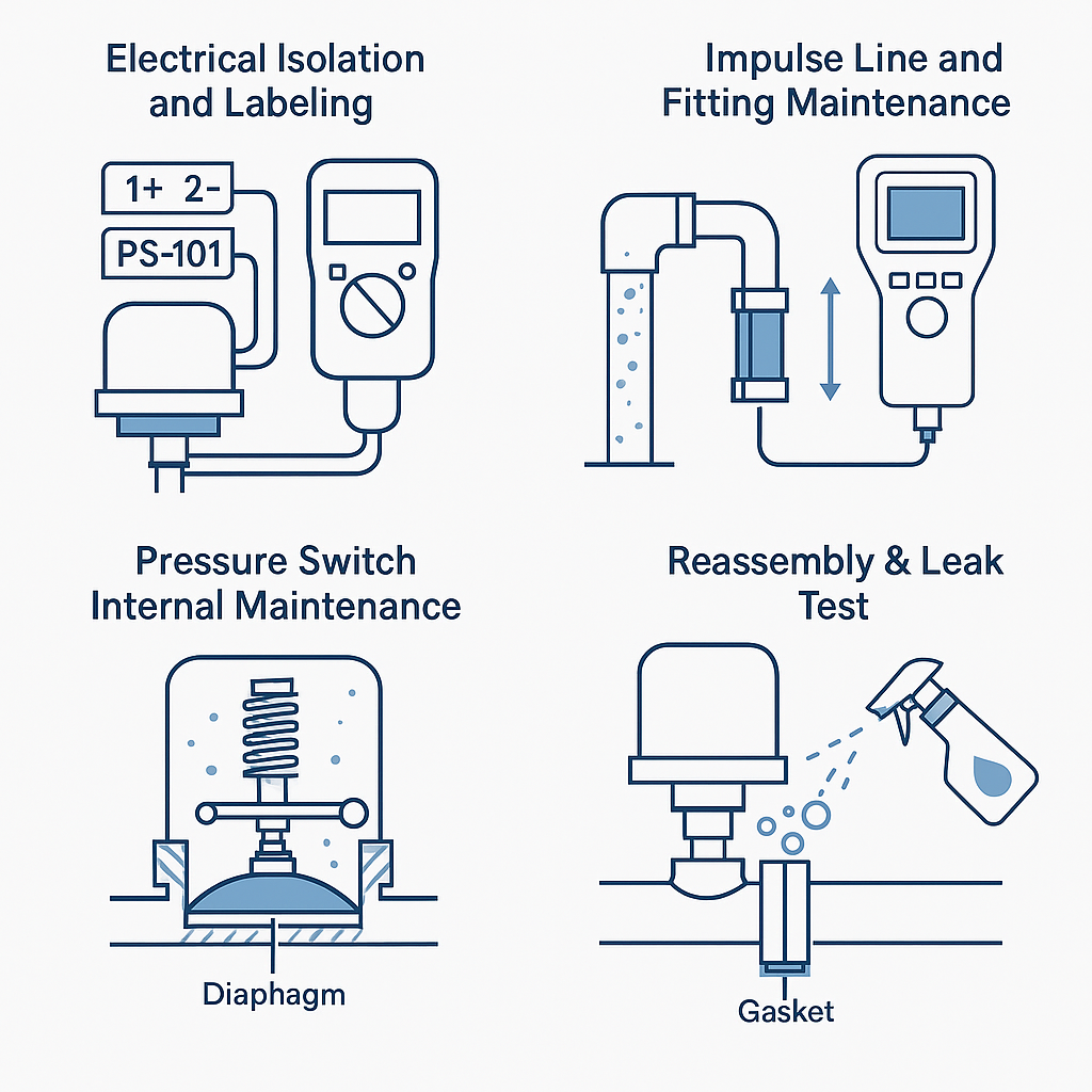
2.1 Electrical Isolation and Labeling
Disconnect the power and confirm zero voltage using a multimeter.
Tag wires and terminals clearly (e.g., “1#”, “2#”, polarity “+/-”, loop number “PS-101”), and photograph connections for reference.
Record current switch settings, including setpoint, reset value, and deadband.
2.2 Root Valve Inspection
Sealing Check: Confirm valve stem movement. Lack of movement after switching may indicate internal jamming.
Packing Gland Maintenance: Tighten packing gland bolts if leakage is found. Replace PTFE packing if leakage persists.
Stem Lubrication: Apply grease to threads and bolts to prevent rust.
Hot Work Note: If the root valve is corroded or fails to seal, request hot work permits and replace the valve after system isolation and purging.
3. Impulse Line and Fitting Maintenance
3.1 Clogging & Corrosion
If medium is present, depressurize the line and observe discharge. Use flushing fluid if a sealing system is installed.
For dry lines, clean using compressed air or soft wire rods (avoid excessive force).
Use ultrasonic thickness testers to check elbows and welded sections. Replace the impulse line if thickness <80% of design.
3.2 Fitting Repairs
Check the internal threads of the pressure switch. Replace damaged threads or fittings if necessary.
For threaded installations requiring welding, confirm no residual pressure or medium is present.
4. Pressure Switch Internal Maintenance
4.1 Inspection & Cleaning
Disassemble the enclosure and check:
Sensing Elements (diaphragm/bellows): cracks, deformation, aging.
Mechanical Transmission: spring elasticity, lever wear, movement flexibility.
Electrical Contacts: oxidation, burning, terminal tightness.
Use anhydrous ethanol to clean components, lubricate moving parts with light oil (e.g., clock oil).
4.2 Calibration & Deadband Test
Adjust setpoint by turning the adjustment knob clockwise (increase) or counter-clockwise (decrease).
Use pressure calibration devices with ≥0.05% accuracy. Test 2–3 times to verify repeatability within ±1% FS.
Trip Point Test:
Rising Pressure: Record switch actuation pressure.
Falling Pressure: Record reset pressure.
Deadband = Actuation – Reset, usually 0.5%–5% FS.
Confirm interlock logic (high/low trip), simulate process signals, and verify interface with DCS/PLC systems (analog or digital I/O).
5. Reinstallation and Commissioning
5.1 Reassembly & Leak Test
Reinstall the switch with proper sealing gaskets (e.g., PTFE or spiral wound gaskets).
Use PTFE tape for threaded connections, tighten explosion-proof housing screws.
Reconnect terminals and verify tightness and grounding.
5.2 Functional Test
Compare DCS/PLC pressure display with local gauge (≤±1.5% FS).
Simulate overpressure to test alarm and shutdown functions.
Use leak detection spray or soap water for joint testing. For high-pressure systems, conduct pressure hold test at 1.1x design pressure for 30 minutes.
Record settings and calibration data, and obtain sign-off from process personnel.
6. Working at Height & Final Checks
6.1 Elevated Work Safety
For tasks >2 meters high, obtain a High-Altitude Work Permit.
Wear safety harnesses, use anti-slip ladders or scaffolding, and secure tools in pouches.
6.2 Final Cleanup & Documentation
Fill in the Maintenance Record Sheet with:
Date, personnel, and equipment ID
Parts replaced (e.g., gasket, packing, connectors)
Calibration and test results
Signatures from maintenance and process supervisors
Restore protective covers and insulation. Properly dispose of waste.
Key Risk Points & Preventive Measures
| Risk | Preventive Measure |
|---|---|
| Medium leakage | Fully depressurize and purge. Use explosion-proof tools. Gas test before hot work. |
| Unintended interlock trigger | Disconnect interlock logic before work. Double-check logic before reactivating. |
| Calibration errors | Use certified equipment. Qualified personnel only. Archive calibration records. |
| Falls from height | Inspect ladders/scaffolding. Anchor safety harness. Assign a spotter for supervision. |