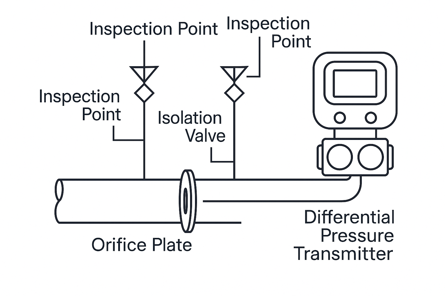
Orifice flowmeters, also known as differential pressure flowmeters, consist of a primary element (such as an orifice plate, nozzle, or Venturi tube) and a transmitter.
Special types like quarter-circle orifice plates, segmental orifice plates, and double orifice plates are used for specific applications. Depending on the fluid characteristics (e.g., corrosive, viscous, or gas-bearing), additional components such as seal pots or elevated transmitter positions may be required.
Illustration 1: Typical Configuration of Orifice Flowmeter (with DP transmitter)
2. Key Steps for Maintenance and Retrofitting
2.1 Pre-Operation Preparation
Process Confirmation:
Coordinate with process department to confirm that dismantling does not trigger interlocks.
Apply for work permits, including high-altitude operation permits if required.
Risk Assessment:
Evaluate pressure, temperature, and corrosiveness.
Use protective gear (e.g., gloves, goggles).
For flammable/explosive media, use explosion-proof tools. Always work in pairs for safety.
2.2 Visual Inspection Checklist
Component
Inspection Items
Impulse Tubes & Valves
Check for corrosion, valve handle integrity, and drain valve blockages
Transmitter
Cleanliness, dryness, terminal corrosion, waterproof sealing, display status
Heat Tracing/Insulation
Operational status, rewrap insulation after repair
Illustration 2: Inspection Points of Orifice Flowmeter System
2.3 Maintenance Points
Orifice Element Cleaning:
Gently clean after removal. Do not use abrasive tools such as sandpaper or files.
Corrosion & Erosion:
Replace if material mismatch or erosion is severe.
Investigate cause of deformation (e.g., stress, improper installation).
Pressure Tapping:
Ensure no blockage in pressure taps or annular chambers. Clean using steam or wire.
Sealing Surfaces & Accessories:
Inspect and record condition of bolts, gaskets, and flanges. Replace if damaged.
2.4 Pressure Testing
With Seal Liquid Systems:
Test for internal leaks, blockage, and joint integrity using seal liquid.
Pressure range: 4.0–5.0 MPa. Do not exceed valve ratings (usually 6.3 MPa).
Without Seal Liquid:
Use manual test pump or compressed air. Ensure system is leak-free.
2.5 Installation Notes
Sealing and Bolting:
Replace gaskets, optionally wrap PTFE tape.
Use elliptical gaskets for high-temp/pressure.
Align flanges and tighten bolts uniformly.
Transmitter Wiring:
Clean terminals. Replace damaged flexible tubing with cable glands.