1. Safety Measures and Preparations
1.1 Basic Safety Requirements
Process Isolation & Power-Off: Disconnect power and signal loop (e.g., DCS) before maintenance.
Explosion-Proof Precautions: Use explosion-proof tools in hazardous zones; never open housing when powered.
Personal Protective Equipment (PPE): Use insulating gloves, anti-scalding gear, and chemical-resistant suits when needed.
1.2 Tools and Documentation Checklist
| Item | Purpose |
|---|---|
| Multimeter | Check voltage and loop current |
| Signal Generator | Simulate input (RTD/Thermocouple) |
| Explosion-Proof Wrench | Open transmitter housing safely |
| Product Manual | Wiring diagrams, calibration tables |
| Resistance Table | For Pt100, K-type values vs. temperature |

2. Visual Inspection and Installation Check
2.1 External and Component Inspection
Housing: No deformation or cracks; gaskets intact.
Nameplate: Model, range, and Ex rating clearly readable.
Terminals: Rust-free, tightly connected; insulation intact.
2.2 Installation Conformity
Vibration: Install away from heavy vibration; use damping bracket if needed.
Insertion Depth: RTD tip should reach ½ to ⅔ of pipe diameter.
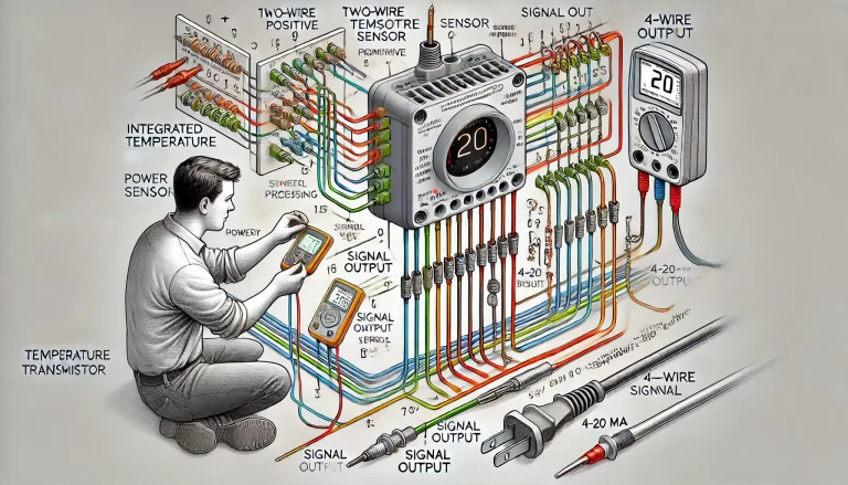
Wiring: Follow manual; polarity and intrinsic safety loop must be correct.

3. Calibration and Function Testing
3.1 Calibration Setup
Disconnect from control system.
Use:
Resistance Box for RTDs
mV Signal Generator for thermocouples
3.2 Zero & Span Adjustment (Pt100 Example)
| Calibration Point | Input (Ω) | Expected Output (mA) | Allowable Error |
|---|---|---|---|
| 0°C | 100.0 | 4.00 | ±0.08 mA |
| 200°C | 177.1 | 20.00 | ±0.4 mA |
3.3 Linearity Verification
Test at 0%, 25%, 50%, 75%, 100% of range during both upscale and downscale checks. Output error should be ≤±0.5% FS.

4. Fault Diagnosis Procedures
| Fault Symptom | Diagnostic Steps |
|---|---|
| 0 mA or ∞ Output | Check 24V supply, sensor input, wiring terminals |
| Output Too High or Low | Verify input signal; recalibrate; check sensor drift |
| Unstable Output | Check wiring, EMI, component moisture or corrosion |
| Control Room Display Error | Check isolator (safety barrier), DCS channel, insulation resistance ≥50MΩ |
5. Special Scenarios
Intrinsic Safety Zones: Power off isolator, check resistance with EX-rated multimeter
High Temp / Humidity: Replace hardened seals; use sun/rain covers
Vibration Environments: Use locknuts, check bracket tightness regularly
6. Reinstallation and Commissioning
Wiring: Tight and secure; excess wire must be tied.
Explosion-Proof Housing: Use gland seals; tighten bolts.
System Test: Check both local display and DCS signal; deviation ≤±0.5% FS.
Interlock Simulation: Test alarms, auto shutoffs, etc.

7. Documentation and Maintenance Plan
7.1 Sample Calibration Record
| Point | Input (Ω/mV) | Output (mA) | Error Before | Error After |
|---|---|---|---|---|
| 0°C | 100.0 | 4.02 | +0.5% | 0% |
| 200°C | 177.1 | 19.85 | –0.75% | 0% |
7.2 Maintenance Plan
Routine Check: Weekly external check, box seal, and display.
Recalibration: Every 6–12 months; 3 months in harsh conditions.
Spare Parts: Gaskets, terminals, full transmitter units.
8. Key Risks and Prevention
| Risk | Preventive Measures |
|---|---|
| Explosion-Proof Failure | Never modify structure; reseal housing properly |
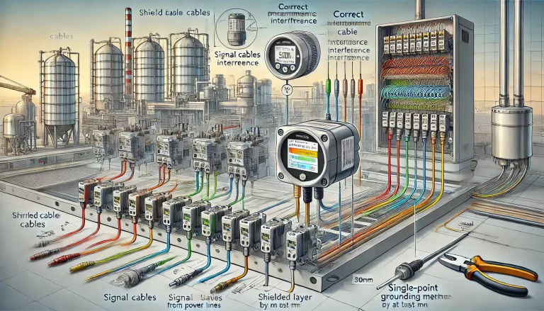
| Signal Interference | Use shielded cable, ≥30 cm from power lines |
| Calibration Error | Use traceable, certified equipment |

9. Real-World Fault Case Studies
Case 1: Inaccurate Temperature Reading Due to Moisture
Scenario: A Honeywell integrated transmitter in a chemical plant reactor showed readings significantly lower than the actual temperature.
Diagnosis: Moisture and frost found inside the terminal box led to insulation degradation.
Solution: Moisture was removed, the device was dried and rewired. Readings normalized.
Lesson: Regularly inspect seal integrity and apply moisture-proofing for outdoor or humid environments.
Case 2: No Output from Newly Installed Transmitter
Scenario: A Rosemount transmitter in a power plant retrofit failed to output any signal after installation.
Diagnosis: Configuration mismatch—transmitter was programmed for 4-wire RTD, but the sensor used was 3-wire; incorrect wiring observed.
Solution: Rewired to 3-wire standard, reprogrammed transmitter. Output restored.
Lesson: Carefully verify wiring type and match configuration during installation; always cross-check wiring diagrams.
Case 3: Frozen Temperature Indication
Scenario: An E+H transmitter in a wastewater plant showed a fixed reading despite varying water temperatures.
Diagnosis: Internal failure of the transmitter confirmed after isolating other components.
Solution: Replaced with a new identical model. Real-time tracking restored.
Lesson: For critical points, stock spares to avoid process downtime due to hardware failure.
Case 4: Severe Signal Fluctuations
Scenario: A Siemens transmitter on a kiln reported highly unstable temperatures (fluctuating from 910°C to 987°C).
Diagnosis: Oxidized, moldy signal wires and loose terminals were identified.
Solution: Cleaned terminals, replaced damaged wires, ensured secure connections. Signal stabilized.
Lesson: Maintain clean, tight connections. Periodically inspect wiring in high-heat or dusty areas.

10. Conclusion: Reliable Temperature Measurement Starts with Reliable Maintenance
Integrated temperature transmitters are vital for stable industrial process control. Their reliability hinges on proper installation, periodic calibration, environmental protection, and timely fault handling.
By following the comprehensive procedures outlined in this guide, technicians can minimize downtime, avoid hazardous incidents, and ensure accurate temperature monitoring across a wide range of applications—from chemical reactors to wastewater treatment plants and high-temperature kilns.
